Page 206 - Softbound_Edition_19_en
P. 206

Solenoid operated spool valve
                                                                                Solenoid operated spool valve                                                                                                Solenoid operated spool valve


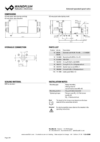
       DIMENSIONS                                                                                                                  Solenoid operated spool valve
       4/3-way spool valve (spring centring)               4/2-way spool valve (spring reset)                                      Flange construction                                  NG6
       4/2-way spool valve (impulse)                                                                                                                                                    ISO 4401-03
                                                                                                                                    ◆  4/2-way impulse valve
                                                                                             9.5
                                                                    110                                                             ◆  4/3-way with spring centred mid position         x II 2 G Ex db IIC T6, T4
                                                                                             5.2
                                                                                                    MD= 5.2Nm                       ◆  4/2-way with spring reset                        x II 2 D Ex tb III C T80 °C, T130 °C
                                                                 70.8                                   7                           ◆  Q  = 80 l/min                                    x I M2 Ex db I Mb
                                                                                                                                       max
                                                              93.8   15                                                             ◆  p  = 350 bar                                     Class I Division 1
                                                                                                                                       max
                                                                 MD=5.5Nm                                46                                                                             Class I Zone 1
                                                                                                        39
                                                                 23
             10                                                     12  17  18 10 18        70       40
                           245.9                                 MD=9Nm                                MD=50Nm
                                                                                60      5                                          DESCRIPTION                                          APPLICATION
                                                                               89           68        12.6                         Direct operated solenoid spool valve with 4 connections in 5 cham-  These  valves  are  suitable  for  applications  in  explosion-hazard
                                                                                     169.6                                         ber design. With the solenoids deenergised, the spool is held in the   areas, open cast and also in mines. Spool valves are mainly used for

                                                                                                                                   center position by the spring (4/3), or switched back to the offset   controlling direction of movement and stopping of hydraulic cylin-
       HYDRAULIC CONNECTION                                PARTS LIST                                                              position (4/2). With the impulse spool (4/2), the spool is held in the   ders and motors. The direction of movement is determined by the


                                                             Position Article  Description                                         switching position by the detent. The pressure tight encapsulated   position of the spool and its symbol.
                                 17.8                                                                                              Ex-protection  solenoid  coil  prevents  an  explosion  on  the  inside
                                                                 10 263.64..  Solenoid coil MK.45 / 18 x 60-… /  L15-M238          penetrating to the outside as well as an ignitable surface tempera-
                            T                                       263.68..                                                       ture.


                        A       B                                12 154.2603  Knurled nut Ex M18 x 1,5 x 18
                    31                     21    32.5                                                                              CERTIFICATES                                         ACTUATION
                                                                 15 253.8028  HB6-Z591
                            P                                    17 160.2251  O-ring ID 25,07 x 2,62 (NBR)                                   Surface  Mining   Standard      Z604        Actuation          Switching solenoid, wet pin push type,
                          21.5                                   18 160.0171  O-ring ID 17,17 x 1,78 (polyurethan)                                            -25 °C to…  -40 °C to…                        pressure tight
                            40.5                                                                                                    ATEX       x       x          x           x          Execution          MKY45 / 18x60 (data sheet 1.1-183)
                                                                 40 239.2210  Socket head screw M20 x 1                                                                                                     MKU45 / 18x60 (data sheet 1.1-184)
                                                                 70 160.0091  O-ring ID 9,25 x 1,78 (polyurethan)                   IECEx      x       x          x           x          Connection         Cable gland for cable Ø 6,5…14 mm
                                                                                                                                    CCC        x       x          x           x
                                                                110 111.1080  Cable gland M20 x 1,5
                                                                                                                                    EAC        x       x          x           x         Attention!  The UL execution is always supplied without cable
                                                                                                                                                                                                 gland
                                                                                                                                    Australia  x       x          x           x
                                                                                                                                    MA                 x          x
       SEALING MATERIAL                                    INSTALLATION NOTES                                                       UL / CSA   x                  x           x
       NBR as standard                                      Mounting type      Flange mounting                                     The certificates can be found on www.wandfluh.com
                                                                               4 fixing holes for
                                                                               socket head screws M5 x 45
                                                            Mounting position  Any, preferably horizontal                          SYMBOL
                                                            Tightening torque  Fixing screws M  = 5,1 Nm (screw
                                                                                           D
                                                                               quality A4)                                                    AB3                     AB1                    AB2
                                                                               M  = 9 Nm knurled nut                                         A B                        A B               A B
                                                                                D
                                                           Note!    The length of the fixing screw depends on the base              a   a     b      b         a    a    b     b      a   a     b      b
                                                                    material of the connection element.                                      P T                        P T               P T


                                                           Attention!  For stack assembly please observe the remarks in the                  ACB                      AC1                    CB2
                                                                    operating instructions                                                   A B                        A B               A B
                                                                                                                                         a    o    b                a    b                  a   b
                                                                                                                                    a                    b     a               b      a                b
                                                                                                                                             P T                        P T               P T


                                                                                                                                             ADB                      AD1                    DB2
                                                                                                                                             A B                        A B               A B
                                                                                                                                              o                           b                 a
                                                                                                                                         a         b                a                           b
                                                                                                                                    a                    b    a                b      a                b
                                                                                                                                             P T                        P T               P T
                                                           Wandfluh AG  Postfach  CH-3714 Frutigen
                                                           Tel. +41 33 672 72 72  Fax +41 33 672 72 12  [email protected]

                           www.wandfluh.com  Illustrations are not binding  Data subject to change  4/4  Edition: 21 24  1.3-33 E                      www.wandfluh.com  Illustrations are not binding  Data subject to change  1/5  Edition: 21 05  1.3-34 E
       Page 206
   201   202   203   204   205   206   207   208   209   210   211