Page 236 - Softbound_Edition_19_en
P. 236

Solenoid operated spool valve
                                                                                Solenoid operated spool valve                                                                                                Solenoid operated spool valve


       PERFORMANCE SPECIFICATIONS                                                                                                  DIMENSIONS
       Oil viscosity u = 30 mm /s                                                                                                  4/3-way valve (spring centred)                       4/2-way valve (spring reset)
                       2
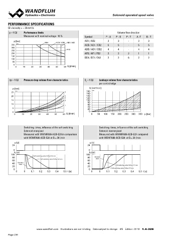
       p = f (Q)  Performance limits                                               Volume flow direction                                       A                       B                                   A                    9.5   130
                                                                                                                                                                                                                                   140
                  Measured with nominal voltage -10 %       Symbol         P - A  P - B  P - T   A -T  B - T                                        100 140  120                                                  MD=5.2Nm     5.2
                                                                                                                                                                                                                                E   8
           p [bar]              BEA     ACB / ADB  AB1 / AB2  AB1 / AB2      3      3      -      3      3
         350  K1041                                         ACB / AC1 / CB2  5      5      -      5      5                                                                                83
         300                                                ADB / AD1 / DB2  4      4      -      4      4                                                                                  45
         250                                    AFB                                                                                                                                          W =                                    41    49
         200                                                AFB / AF1 / FB2  2      2      2      1      1
         150                                                BEA / BE1 / EA2  2      2      6      2      2
         100                                                                                                                               10                                               70   60    10          50
          50                                                                                                                                               208
           0                                                                                                                                                                               MD=5Nm   20    50           68       13
            0    10    20    30   40    50    60  Q [l/min]                                                                            HF1   51                HS1   57                                         151
                                                                                                                                              37                       37
                                                                                                                                                                               90
                                                                                                                                                     80                                                A
       Δp = f (Q)  Pressure drop volume flow characteristics  Q  = f (Q)  Leakage volume flow characteristics
                                                             L
                                                                      per control edge
                                                                                                                                                                                           86
          p [bar]                                               Q [cm /min]                                                                                                                45
                                                                    3
         25  K1042                            6              180  K1043
                                                             160                                                                                                                            M =
         20                                   5              140
                                              4              120
         15                                 3  2             100                                                                                                                                       10
         10                                                   80
                                                              60
                                              1               40                                                                                                                                  17      53
          5                                                   20                                                                                                                                                151
          0                                                    0                                                                                                                        E = Air bleed screw
           0    10    20    30    40   50    60  Q [l/min]       0   50   100  150  200  250  300  350 p [bar]
                                                                                                                                                                                        Orifices in valve body influence the switching times

                                                                                                                                   HYDRAULIC CONNECTION                                 PARTS LIST
                  Switching  times, influence of the soft switching     Switching  times, influence of the soft switching
                  Solenoid energised                                  Solenoid deenergised                                                                                               Position Article  Description
                  Measured with WWMFA06-ACB-G24 in comparison         Measured with WWMFA06-ACB-G24 compared                                                 17.8                             10 206.1...  W.E45 / 23 x 50
                  with WDMFA06-ACB-G24 at Q = 30 l/min                with WDMFA06-ACB-G24  at Q = 30 l/min                                             T                                        206.7...  M.S45 / 23 x 50

           U [V]                                                U [V]                                                                                A       B                                50 160.2093  O-ring ID 9,25 x 1,78 (NBR)
          24                                                  24                                                                                 31                     21    32.5               160.6092  O-ring ID 9,25 x 1,78 (FKM)
          0                                                    0                                                                                        P                                     60 160.2222  O-ring ID 22,22 x 2,62 (NBR)
           p  [bar]                                             p  [bar]
                                                                E
            E
         100  K1051_e   Soft-switching valve Orifice 0,5 mm  100  K1052_e                                                                             21.5                                    70 154.2701  Knurled nut M23 x 1,5 x 19,7
          80                 Soft-switching valve Orifice 0,3 mm  80  Standard                                                                          40.5                                  80 253.7004  Push-button
                                                                    Valve
          60                                                  60
          40  Standard                                        40                                                                                                                              90 253.7002  Spindle
              valve
          20                                                  20                  Soft-switching valve Orifice 0,5 mm                                                                        100 246.1012  Socket head screws zinc-coated blue
          0                                                    0               Soft-switching valve Orifice 0,3 mm                                                                                       DIN84A M4 x 12
            0     0    0,1  0,2   0,3   0,4  0,5 t [s]           0    0    0,1   0,2   0,3   0,4  0,5 t [s]
                                                                                                                                                                                             120 118.1023  Orifice M4 / 0,5 x 4St

                                                                                                                                                                                                 118.1029  Orifice M4 / 0,3 x 4St
                                                                                                                                                                                             130 246.1007  Socket head screw zinc-coated blue M4 x 6
                                                                                                                                                                                                         DIN84 A
                                                                                                                                                                                             140 049.2040  Bonded seal ID 4,1 x 7,2 x 1


                                                                                                                                                                                        Wandfluh AG  Postfach  CH-3714 Frutigen
                                                                                                                                                                                        Tel. +41 33 672 72 72  Fax +41 33 672 72 12  [email protected]

                           www.wandfluh.com  Illustrations are not binding  Data subject to change  4/5  Edition: 22 10  1.4-32 E                      www.wandfluh.com  Illustrations are not binding  Data subject to change  5/5  Edition: 22 10  1.4-32 E
       Page 236
   231   232   233   234   235   236   237   238   239   240   241