
Page 734 - Softbound_Edition_19_en
P. 734
1 2 3 4
17 18 19 20
21 22 23 24
5 6 7 8
FUNCTION
SUPPLY
ERROR
FIELDBUS X4
USB
9 10 11 12 25 26 27 28
13 14 15 16 29 30 31 32 A B C A B 99 105
D
D C
45 114
Digital amplifier module SD7 Digital amplifier module SD7
Digital amplifier module
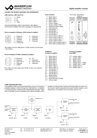
CONNECTOR WIRING DIAGRAM / PIN ASSIGNMENT Command value scaling Mode of operation «Command value bipolar (2-sol)»
The command value can be applied as a voltage, current or digital si- Dependent on a bipolar command value signal (voltage), according to
USB-interface, USB Type B X2 Basic amplifier - Basic Analog - Basic fieldbus gnal, or via fieldbus. For every command value, the input utilised can the signal level one of the two solenoids is driven. The switching thres-
- Enhanced
B
A
1 = VBUS 1 = Digital input 1 be selected. The scaling takes place via the parameters «Interface» hold between the two solenoids as standard is at 0V (e.g. -10….+10V
5
9 2 = D - 6 1 2 = Digital input 2 and «Reference». Furthermore every command value can be monito- correspond to -100….+100 % command value, -100…0 % command
A
3 2 8 4 3 7 2 3 1 2 3 4 17 18 19 20
B
4 1 7 3 = D+ 8 4 3 = Digital output 1 5 6 7 8 21 22 23 24 red for a cable break (except for voltage and digital signal). For every value correspond to Imin….Imax solenoid driver 2, 0….+100 % com-
2
6 9 4 = Digital output 2 command value a dead band can also be set. Optionally one can ope- mand value correspond to Imin….Imax solenoid driver 1).
4 = GND 5
1
5 = Supply voltage + rate with two command values. The characteristic of these command
17 18 19 20
1 2 3 4
1 2 3 4
17 18 19 20
The parameterisation cable is not included in the delivery 6 = Supply voltage 0 VDC 5 6 7 8 21 22 23 24 values can be adjusted. 5 6 7 8 21 22 23 24
(commercially available USB cable, plug type A to plug type B) 7 = Stabilised output voltage
8 = Analog ground Fixed command values
9 = Analog input 1+ • For the Basic amplifier, 3 fixed command values are available,
10 = Analog input 1 - which can be selected via 2 digital inputs. Changeover
threshold
Device receptacle CANopen, J1939 (male) X4 (option) 11 = Analog input 2+ FUNCTION L • For the Enhanced amplifier, 7 fixed command values are avai- between the two
solenoids
12 = Analog input 2 - ERROR SUPPLY FIELDBUS X4 ERROR FUNCTION SUPPLY lable, which can be selected via 3 digital inputs.
FUNCTION
SUPPLY
ERROR
5 1 1 = Reserved 6 = Reserved 13 = Output solenoid driver 2 + FIELDBUS X4 FIELDBUS X4
9 6 14 = Output solenoid driver 2 - Command value generator Command value
3 2 4 2 2 = CANLow 7 = CANHigh
8 3 7 3 3 = CANGnd 8 = Reserved 15 = Output solenoid driver 1 + For each solenoid output two linear ramps for up and down are avai- Analogue value
USB
9 10 11 12 25 26 27 28
4 1 7 2 8 4 4 = Reserved 9 = Reserved 16 = Output solenoid driver 1 – USB USB lable which can be adjusted separately.
C
6 9 9 10 11 12 25 26 27 28 9 10 11 12 25 26 27 28 13 14 15 16 29 30 31 32
1 5 5 = CANShield 21 = HART (option) Analog input 3 + 13 14 15 16 29 30 31 32
13 14 15 16 29 30 31 32
22 = HART (option) Analog input 3 - D HOLD command value (fieldbus only) Mode of operation «Command value unipolar (2-sol with DigInp)»
If via Profibus DP the device is put into the «HOLD» state, the respec- Dependent on a unipolar command value signal (voltage, current), the
C
D
The mating connector (plug female, DSUB, 9-pole) is not included tive command value is activated. solenoid is driven by solenoid driver 1, when the selected digital input
in the delivery. is «not activated», resp. the solenoid by the solenoid driver 2, when the
Valve type selected digital input is «activated» (e.g. 0….10V correspond to 0….100
Additional Enhanced amplifier Here the mode of operation is set. It is also possible to select whether % command value, 0....100 % command value correspond to Imin….
Enhanced amplifier with HART proportional or switching solenoids are to be controlled. Imax solenoid driver 1 or 2).
Device receptacle Profibus (female) X4 (option)
17 = Digital input 3 17 = Analog output + Mode of operation «Command value unipolar (1-sol)»
5 1 = Reserved 6 = VP 18 = Digital input 4 18 = Analog output - Dependent on a unipolar command value signal (voltage, current), the
1
9 6 2 = Reserved 7 = Reserved 19 = Digital input 5 19 = Digital input 3 solenoid is driven (e.g. 0...10V correspond to 0...100 % command va-
2
3 2 8 4 3 7 3 = RxD / TxD - P 8 = RxD / TxD - N 20 = Digital input 6 20 = Digital input 4 lue, 0...100 % command value correspond to Imin...Imax solenoid dri-
3
4 1 7 2 8 4 = Reserved 9 = Reserved 21 = Digital input 7 21 = Analog input 3 + HART ver 1).
4
6 9 22 = Digital input 8 22 = Analog input 3 - HART
5
1 5 = DGND
23 = Digital output 3 23 = Analog input 4 +
The mating connector (plug male, DSUB, 9-pole) is not included 24 = Digital output 4 24 = Analog input 4 -
in the delivery. 25 = Analog input 3 + Command value
26 = Analog input 3 -
27 = Analog input 4 + Analogue value
28 = Analog input 4 -
29 = Digital ground Changeover between the two
30 = Analog ground solenoids by means of the selected digital input
31 = Stabilised output voltage Command value
32 = Analog output
Analogue value Signal recording
The SD7 amplifier module has a signal recording function. This, by
FUNCTION DESCRIPTION means of PASO, enables the recording of various system signals, such
The amplifier module can be parameterised by means of the parame- enables the setting of the most important parameters by means of ro- Mode of operation «Command value unipolar (2-sol)» as command value, solenoid currents, etc., which can be represented
terisation software «PASO» through the USB-interface. In addition, tary selector switch and push-buttons and therefore makes a com- Dependent on a unipolar command value signal (voltage, current), ac- on a common time axis.
the parameterisation software makes a data analysis possible. Optio- missioning of the amplifier module possible without a PC. cording to the signal level one of the two solenoids is driven. The swit-
nally the amplifier module is equipped with a manual operation, which ching threshold between the two solenoids as standard is in the middle Solenoid driver
of the values range of the command value signal (e.g. 0….10V corre- Two Pulse-Width-Modulated current outputs are available. To each out-
spond to -100….+100 % command value, -100....0 % command value put, a dither signal is superimposed, whereas dither frequency and
correspond to Imin….Imax solenoid driver 2, 0….+100 % command dither level can be adjusted separately. For each output, the minimum
(Imin) and maximum (Imax) current can be adjusted separately. The
HOLD Fieldbus only value correspond to Imin….Imax solenoid driver 1). solenoid outputs can also be configurated as switching outputs. The-
Command Solenoid output rewith for each output a power reduction can be adjusted separately.
value Solenoid
driver 1
Current measurement
Optimisation of characteristic curve
Command A characteristic curve adjustable per solenoid «Command value input
value 1 Changeover – solenoid current output» enables an optimised (e.g., linearised) cha-
Command Fixed Command DigInp threshold racteristic of the hydraulic system.
Command value command value Valve between the two
value 2 Scaling values generator type Enable Error solenoids
Solenoid output Command value
DigInp DigInp DigInp DigInp Solenoid
driver 2 Current measurement Analogue value
Selection Error Number Enable Solenoid 2
DigInp
Enable Error
Wandfluh AG Tel. +41 33 672 72 72 [email protected] Illustrations not obligatory Data sheet no. Wandfluh AG Tel. +41 33 672 72 72 [email protected] Illustrations not obligatory Data sheet no.
Postfach Fax +41 33 672 72 12 www.wandfluh.com Data subject to change 1.13-101E 4/10 Postfach Fax +41 33 672 72 12 www.wandfluh.com Data subject to change 1.13-101E 5/10
CH-3714 Frutigen Edition 23 02 CH-3714 Frutigen Edition 23 02
Page 734