Page 190 - Softbound_Edition_19_en
P. 190

Solenoid operated spool valve
                                                                                Solenoid operated spool valve                                                                                                Solenoid operated spool valve


       ELECTRICAL SPECIFICATIONS                           HYDRAULIC SPECIFICATIONS                                                DIMENSIONS                                           HYDRAULIC CONNECTION
       Protection class   Connection execution D: IP65      Working pressure   p  = 350 bar                                        4/2-way spool valve (spring reset)                   Cavity drawing according to Wandfluh standard
                                                                                max
                          Connection execution J: IP66      Maximum volume flow  Q  = 38 l/min
                                                                                max
                          Connection execution G: IP67 and IP69K  Fluid        Mineral oil, other fluid on request                                          s27  7/8"-14UNF-2A                                    7/8"-14 UNF
       Relative duty factor  100 % DF                       Viscosity range    12 mm /s…320 mm /s
                                                                                   2
                                                                                            2
       Switching frequency  15'000 / h                      Temperature range   -25…+70 °C (NBR)                                      62.9   45                   (4)  (3)  (2)  (1)
       Service life time  10  (number of switching cycles,   fluid             -20…+70 °C (FKM)                                          W =                                                                        (4)
                            7
                          theoretically)                    Contamination      Class 20 / 18 / 14                                                                                                                   (3)
       Voltage tolerance  ± 10 % with regard to nominal voltage  efficiency                                                            12   17    10           50  70  60 90  80  100 110
       Standard nominal   12 VDC, 24VDC, 115 VAC, 230 VAC   Filtration         Required filtration grade ß 10…16 ≥ 75,               MD=5Nm                                                                         (2)
       voltage            AC = 50 to 60 Hz, rectifier integrated in            see data sheet 1.0-50                                        19.7    50.5
                          the connector socket                                                                                                      84.1             63                                      (1)
                                                                                                                                                           147.1
       Note!   Other electrical specifications see data sheet 1.1-182                                                                                                                   Attention!  For detailed cavity drawing and cavity tools see data
               (slip-on coil W) and 1.1-181 (slip-on coil M)                                                                                                                                     sheet 2.13-1057


                                                                                                                                      77.2
                                                                                                                                       45
                                                                                                                                        M =
       PERFORMANCE SPECIFICATIONS
                       2
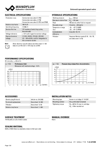
       Oil viscosity u = 30 mm /s                                                                                                                 10

       p = f (Q)  Performance limit                         Δp = f (Q)  Pressure drop volume flow characteristics
                  Measured with nominal voltage  -10 %                                                                             PARTS LIST
                                                               p [bar]
           p [bar]                                            30  K4171                                                              Position Article  Description
         350  K4170                                           25                                                                         10 206.1...  W.E45 / 23 x 50
         300                                                  20
         250                                                  15                                                                            206.7...  M.S45 / 23 x 50
         200                                                  10                                                                         12 154.2701  Knurled nut M23 x 1,5 x 19,7
         150                                                                                                                             17 160.2222  O-ring ID 22,22 x 2,62 (NBR)
         100                                                  5
          50                                                  0                                     Q [l/min]                            50 160.2187  O-ring ID 18,72 x 2,62 (NBR)
           0                                                    0   5   10  15   20  25  30  35   40
            0   5   10  15   20  25  30  35   40  Q [l/min]                                                                              60 160.2156  O-ring ID 15,60 x 1,78 (NBR)
                                                                                                                                         70 049.8196  Backup ring PTSM rd 14,5 x 17,4 x 1,4
                                                                                                                                         80 160.2140  O-ring ID 14,00 x 1,78 (NBR)
                                                                                                                                         90 049.8177  Back-up ring PTSM rd 12,4 x 15,3 x 1,4
                                                                                                                                        100 160.2120  O-ring ID 12,42 x 1,78 (NBR)
       ACCESSORIES                                         INSTALLATION NOTES
                                                                                                                                        110 049.8166  Backup ring PTSM rd 10,8 x 13,7 x 1,4
                                                                                             7
       Electric plug B (black)      Article no. 219.2002    Mounting type      Screw-in cartridge  ⁄8 “-14 UNF
       Technical explanations       Data sheet 1.0-100      Mounting position  Any, preferably horizontal
       Filtration                   Data sheet 1.0-50       Tightening torque  M  = 60 Nm Screw-in cartridge
                                                                                D
       Relative duty factor         Data sheet 1.1-430                         M  = 5 Nm knurled nut
                                                                                D


       SURFACE TREATMENT                                   MANUAL OVERRIDE

       ◆  All parts are zinc-nickel coated                 None


       SEALING MATERIAL
       NBR or FKM (Viton) as standard, choice in the type code


                                                                                                                                                                                        Wandfluh AG  Postfach  CH-3714 Frutigen
                                                                                                                                                                                        Tel. +41 33 672 72 72  Fax +41 33 672 72 12  [email protected]

                         www.wandfluh.com  Illustrations are not binding  Data subject to change  2/3  Edition: 17 50  1.2-210 E                      www.wandfluh.com  Illustrations are not binding  Data subject to change  3/3  Edition: 17 50  1.2-210 E
       Page 190
   185   186   187   188   189   190   191   192   193   194   195