Page 196 - Softbound_Edition_19_en
P. 196

Solenoid operated spool valve
                                                                                Solenoid operated spool valve                                                                                                Solenoid operated spool valve


       PERFORMANCE SPECIFICATIONS                                                                                                  INSTALLATION NOTES                                   STANDARDS
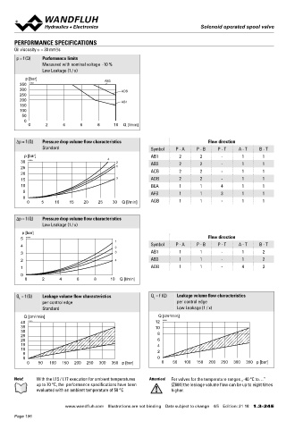
       Oil viscosity u = 30 mm /s                                                                                                   Mounting type      Flange mounting                   Explosion protection  Directive 2014 / 34 / EU (ATEX)
                       2
       p = f (Q)  Performance limits                                                                                                                   3 fixing holes for                Flameproof enclosure  EN / IEC / UL 60079-1, 31
                  Measured with nominal voltage  -10 %                                                                                                 socket head screws M5 x 40 or M5 x 50   Cable entry  EN 60079-0, 1, 7, 15, 31
                  Low Leakage (1 / x)                                                                                                                  (with distance plate BDP4/12)     Mounting interface  Wandfluh standard
                                                                                                                                    Mounting position  Any, preferably horizontal
           p [bar]                        AB3                                                                                                                                            Protection class   EN 60 529
         350  K1028                                                                                                                 Tightening torque  Fixing screws M  = 5,2 Nm (screw   Contamination     ISO 4406
                                                                                                                                                                   D
         300                                     ADB                                                                                                   quality 8.8, zinc coated)         efficiency
         250                                                                                                                                           M  = 9 Nm knurled nut
                                                                                                                                                        D
         200                                     AB1
         150                                                                                                                       Note!    The length of the fixing screw depends on the base   ACCESSORIES
         100                                                                                                                                material of the connection element.
          50                                                                                                                                                                             Fixing screws                Data sheet 1.0-60
           0                                                                                                                                                                             Threaded subplates           Data sheet 2.9-10
            0      2      4      6     8      10  Q [l/min]                                                                        Attention!  For stack assembly please observe the remarks in the
                                                                                                                                            operating instructions                       Multi-station subplates      Data sheet 2.9-50
                                                                                                                                                                                         Module type manifold blocks  Data sheet 2.9-90
       Δp = f (Q)  Pressure drop volume flow characteristics                       Flow direction                                                                                        Technical explanations       Data sheet 1.0-100
                  Standard                                  Symbol    P - A   P - B    P - T   A - T   B - T
                                                                                                                                                                                         Filtration                   Data sheet 1.0-50
           p [bar]                                          AB1        2        2       -       1       1                                                                                Relative duty factor         Data sheet 1.1-430
         30  K1029                         4   2            AB3        2        2       -       1       1                          SEALING MATERIAL
         25                                    1                                                                                   NBR or FKM (Viton) as standard, choice in the type code
         20                                                 ACB        2        2       -       1       1
         15                                    3            ADB        2        2       -       1       1
         10                                                 BEA        1        1       4       1       1                          DIMENSIONS
          5                                                 AFB        1        1       3       1       1                          4/3-way spool valve (spring centring)                4/2-way spool valve (spring reset)
          0                                                                                                                        4/2-way spool valve (impulse)
            0    5     10   15    20    25   30  Q [l/min]  AGB        1        1       -       1       1                                                                                                                       9.5
                                                                                                                                                                                                 110
                                                                                                                                                                                                                               5.2   MD=5.2Nm
       Δp = f (Q)  Pressure drop volume flow characteristics                                                                                                                                    70.8                               6
                  Low Leakage (1 / x)                                                                                                                                                      101.3    93.3
          p [bar]                                                                                                                                                                                                                  32   38    49.5
         5  K1030                                                                  Flow direction                                                                                               22.5
                                              1
         4                                    2             Symbol    P - A   P - B    P - T   A - T   B - T                                                                                15     12 17  18  10 18   50 70
         3                                    3             AB1        1        1       -       1       2                               10          50                                   MD=5.5Nm MD=9Nm                              11.5
         2                                    4             AB3        1        1       -       1       2                                               237                                                   60      5    54   40 MD=50Nm
         1                                                  ADB        1        1       -       4       3                          Dimensions of the solenoid coil see data sheet 1.1-183 and 1.1-184       90.1         57.2    8.1
         0                                                                                                                         The distance plate BDP4/12 has to be ordered separately                       155.4
           0      2     4      6      8     10  Q [l/min]


                                                                                                                                   PARTS LIST                                           HYDRAULIC CONNECTION
       Q  = f (Q)  Leakage volume flow characteristics      Q  = f (Q)  Leakage volume flow characteristics
         L                                                   L                                                                       Position Article  Description
                  per control edge                                     per control edge                                                                                                                      28
                  Standard                                             Low Leakage (1 / x)                                               10 263.6...  Solenoid coil MK.45 / 18 x 60                          14
                                                                    3
          Q [cm /min]                                          Q [cm /min]                                                               12 154.2603  Knurled nut Ex M18 x 1,5 x 18
               3
         40  K1031                                            12  K1032                                                                  15 253.8001  HB6 Manual override „-25 °C to…”                      P
         35                                                   10                                                                            253.8025  HB6-Z604 Manual override „-40 °C to…”
         30                                                    8                                                                                                                                         A       B       14    27
         25                                                                                                                              17 160.2251  O-ring ID 25,07 x 2,62 (NBR)
         20                                                    6                                                                         18 160.2170  O-ring ID 17,17 x 1,78 (NBR)                     T           T0
         15                                                    4
         10                                                                                                                              40 239.2206  Socket head screw M20 x 1
          5                                                    2
          0                                                    0                                                                         50 173.1450  Distance plate BDP4 / 12
            0   50  100  150  200  250  300  350 p [bar]         0   50  100  150  200  250  300  350 p [bar]                            70 160.2052  O-ring ID 5,28 x 1,78 (NBR)
                                                                                                                                            160.6052  O-ring ID 5,28 x 1,78 (FKM)
       Note!   With the L15 / L17 execution for ambient temperatures   Attention!  For valves for the temperature ranges „-40 °C to…”   110 111.1080  Cable gland M20 x 1,5
               up to 70 °C, the  performance specifications have been   (Z604) the leakage volume flow can be up to eight times
               evaluated with an ambient temperature of 50 °C       higher.                                                                                                             Wandfluh AG  Postfach  CH-3714 Frutigen
                                                                                                                                                                                        Tel. +41 33 672 72 72  Fax +41 33 672 72 12  [email protected]

                           www.wandfluh.com  Illustrations are not binding  Data subject to change  4/5  Edition: 21 18  1.3-24 E                      www.wandfluh.com  Illustrations are not binding  Data subject to change  5/5  Edition: 21 18  1.3-24 E
       Page 196
   191   192   193   194   195   196   197   198   199   200   201