
Page 230 - Softbound_Edition_19_en
P. 230
Solenoid operated spool valve
Solenoid operated spool valve Solenoid operated spool valve
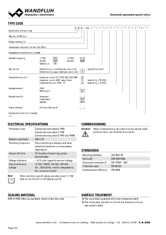
TYPE CODE ACTUATION MANUAL OVERRIDE
W W M F B04 - - / - # Actuation Switching solenoid, wet pin push type, ◆ Integrated (–) Actuation pin integrated in the armature tube.
Spool valve, soft switching pressure tight Actuation by pressing the pin
Execution V.E37 / 19 x 50 (Data sheet 1.1-168) ◆ Push-button (HF1) Integrated in the knurled nut. Actuation by
Slip-on coil, Medium pressing the push-button
N.S35 / 19 x 50 (Data sheet 1.1-175)
Flange construction Connection Connector socket EN 175301 – 803 ◆ Spindle (HS1) Integrated in the knurled nut. Actuation by turning
Connector socket AMP Junior-Timer the spindle (continuously variable valve actuation)
International standard interface ISO, NG 4 The actuation of the manual override is possible up to a
Connector Deutsch DT04 – 2P Attention!
tank pressure of:
Designation of symbols acc. to table
40 bar Integrated (–)
Nominal voltage U N 12 VDC G12 115 VAC R115 40 bar Push-button (HF1)
24 VDC G24 230 VAC R230 100 bar Spindle (HS1)
without coil X5
Slip-on coil Metal housing, round with one-sided collar V (only G12 and G24) PERFORMANCE SPECIFICATIONS
Metal housing, square with one-sided collar N
2
Oil viscosity u = 30 mm /s
Connection execution Connector socket EN 175301-803 / ISO 4400 D p = f (Q) Performance limits Q = f (Q) Leakage volume flow characteristics
L
Connector socket AMP Junior-Timer J (only for U ≤ 75 VDC) Measured with nominal voltage -10 % per control edge
N
Connector Deutsch DT04 - 2P G (only for U ≤ 75 VDC)
N
p [bar] Q [cm /min]
3
Sealing material NBR 350 K1035 AB1 / AB2 60 K1037
ACB
FKM (Viton) D1 300 ADB 50
250 40
Manual override Integrated 200
Push-button HF1 150 30
Spindle HS1 100 20
50 10
Orifice diameter Ø 0.3 mm (Standard) 0 0
0 5 10 15 20 Q [l/min] 0 50 100 150 200 p [bar]
Design index (subject to change)
1.4-23
Δp = f (Q) Pressure drop volume flow characteristics Volume flow direction
ELECTRICAL SPECIFICATIONS COMMISSIONING p [bar] Symbol P - A P - B P - T A - T B - T
Protection class Connection execution D: IP65 Attention! When commissioning, the valve must be vented under 20 K1036 3 AB1 / AB2 3 3 - 3 3
Connection execution J: IP66 pressure (max. two rotations of screw E). 15 2 ACB / AC1 / CB2 3 3 - 3 3
Connection execution G: IP67 and IP69K ADB / AD1 / DB2 2 2 - 1 1
10
Relative duty factor 100 % DF 1
Switching frequency Since switching is damped and slow, 5
switching frequency is of secondary 0
importance. STANDARDS 0 5 10 15 20 Q [l/min]
7
Service life time 10 (number of switching cycles, Mounting interface ISO 4401-02
theoretically) Switching times, influence of the soft switching. Switching times, influence of the soft switching.
Voltage tolerance ± 10 % with regard to nominal voltage Solenoids DIN VDE 0580 Solenoid energised. Solenoid energised.
Standard nominal 12 VDC, 24VDC, 115 VAC, 230 VAC Connection execution D EN 175301 – 803 Measured with WWMFB04-ACB-G24 in compaison Measured with WWMFB04-ACB-G24 in comparison
voltage AC = 50 to 60 Hz, rectifier integrated in Protection class EN 60 529 with WDMFB04-ACB-G24 at Q = 10 l/min with WDMFB04-ACB-G24 at Q = 10 l/min
the connector socket Contamination efficiency ISO 4406
U [V] U [V]
Note! Other electrical specifications see data sheet 1.1-168 24 24
(slip-on coil V) and 1.1-175 (slip-on coil N)
0 0
p [bar] p [bar]
E
E
100 K1050_e 100 K1049_e
80 80 Soft-switching valve
60 Standard valve 60 Standard valve
SEALING MATERIAL SURFACE TREATMENT 40 Soft-switching valve 40
20
20
NBR or FKM (Viton) as standard, choice in the type code ◆ The valve body is painted with a two component paint 0 0
◆ The screw plug, the slip-on coil and the armature tube are 0 0 0,1 0,2 0,3 0,4 0,5 t [s] 0 0 0,1 0,2 0,3 0,4 0,5 t [s]
zinc-nickel coated
www.wandfluh.com Illustrations are not binding Data subject to change 2/4 Edition: 22 09 1.4-23 E www.wandfluh.com Illustrations are not binding Data subject to change 3/4 Edition: 22 09 1.4-23 E
Page 230