
Page 396 - Softbound_Edition_19_en
P. 396
Proportional spool valve
Proportional spool valve Proportional spool valve
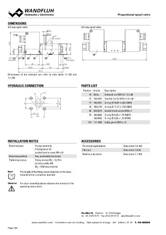
DIMENSIONS Proportional spool valve with additional hand
4/2-way spool valve 4/3-way spool valve lever actuation NG6
9.5 ISO 4401-03
Flange construction
110 5.2 ◆ Q = 35 l/min x II 2 G Ex db IIC
max
MD= 5.2Nm ◆ 4 volume flow levels x II 2 D Ex tD A21 IP65
93.8 7 ◆ Q N max = 25 l/min x I M2 Ex db I Mb
p = 350 bar
◆
Class I Division 1
45 46 max Class I Zone 1
39
23
10
12 17 18 10 18 70 40 269.6
MD=9Nm MD=50Nm
60 10.8 7.6 DESCRIPTION SYMBOL
100.8 68 18.4 Proportional spool valve according to data sheet 1.10-88 with addi- Overview spool types see data sheet 1.10-88
187.2 tional hand lever actuation.
Dimensions of the solenoid coil, refer to data sheet 1.1-183 and Note! The standard valve cannot be retrofitted.
1.1-184
A B
HYDRAULIC CONNECTION PARTS LIST a 0 b
Position Article Description a P T b
17.8
10 263.6... Solenoid coil MK.45 / 18 x 60
T
12 154.2201 Knurled nut Ex M18 x 1,5 x 30 TYPE CODE
A B 17 160.2251 O-ring ID 25,07 x 2,62 (NBR)
31 21 32.5 WD B F A06 - Z568 # 2
18 160.2170 O-ring ID 17,17 x 1,78 (NBR) Spool valve, direct operated
P
40 239.2214 Socket head screw M20 x 1
21.5 70 160.2093 O-ring ID 9,25 x 1,78 (NBR) Proportional, explosion proof execution Ex d
40.5 Flange construction
160.8092 O-ring ID 9,25 x 1,78 (FKM)
110 111.1080 Cable gland M20 x 1,5 International standard interface ISO NG6
Other type designation according to type code data sheet 1.10-88
Hand lever
INSTALLATION NOTES ACCESSORIES Design index (subject to change)
1.10-89
Mounting type Flange mounting Technical explanations Data sheet 1.0-100
4 fixing holes for Filtration Data sheet 1.0-50
socket head screws M5 x 45 Relative duty factor Data sheet 1.1-430 DIMENSIONS GENERAL SPECIFICATIONS
Mounting position Any, preferably horizontal Weight WDBFA06 +1,0 kg
Tightening torque Fixing screws M = 5,2 Nm Note! Further specifications, see data sheet 1.10-88
D
(screw quality A4)
M = 9 Nm knurled nut
D
Note! The length of the fixing screw depends on the base
material of the connection element.
256.5
SURFACE TREATMENT
Attention! For stack assembly please observe the remarks in the
operating instructions ◆ The flange, the housing and the lever are zinc-nickel coated
44.4
167.9 123.5
291.4
Wandfluh AG Postfach CH-3714 Frutigen Wandfluh AG Postfach CH-3714 Frutigen
Tel. +41 33 672 72 72 Fax +41 33 672 72 12 [email protected] Tel. +41 33 672 72 72 Fax +41 33 672 72 12 [email protected]
www.wandfluh.com Illustrations are not binding Data subject to change 6/6 Edition: 21 18 1.10-88S E www.wandfluh.com Illustrations are not binding Data subject to change 1/1 Edition: 19 38 1.10-89 E
Page 396