
Page 728 - Softbound_Edition_19_en
P. 728
Amplifier and controller electronics
Amplifier / controller electronics
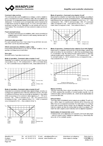
Command value scaling Mode of operation „Command value bipolar (2-sol)“
The command value can be applied as a voltage, current or digital si- Dependent on a bipolar command value signal (voltage), according to
gnal, or via fieldbus For every command value, the input utilised can the signal level one of the two solenoids is driven. The switching thres-
be selected. The scaling takes place via the parameters „Interface“ and hold between the two solenoids as standard is at 0V (e.g. -10….+10V
„Reference“. Furthermore every command value can be monitored for correspond to -100….+100 % command value, -100…0 % command
a cable break (except for digital signal). For every command value a value correspond to Imin….Imax solenoid driver 2, 0….+100 % com-
dead band can also be set. Optionally one can operate with two com- mand value correspond to Imin….Imax solenoid driver 1).
mand values. The characteristic of these command values can be ad-
justed.
Fixed command values
• One fixed command value is available, which can be selected via
a digital input (only DSV electronics with analog interface and 12- Changeover
threshold
pole connector). between the two
solenoids
Command value generator
For each solenoid output two linear ramps for up and down are avai- Command value
lable which can be adjusted separately. Analogue value
HOLD command value (fieldbus option only)
If via Profibus DP the device is put into the “HOLD” condition, the re- Mode of operation „Command value unipolar (2-sol with DigInp)“
spective command value is activated. Dependent on a unipolar command value signal (voltage, current), the
solenoid is driven by solenoid driver 1, when the selected digital input
Valve type is „not activated“, resp. the solenoid by the solenoid driver 2, when the
Here the mode of operation mode is set. selected digital input is „activated“ (e.g. 0….10V correspond to 0….100
% command value, 0....100 % command value correspond to Imin….
Mode of operation „Command value unipolar (1-sol)“ Imax solenoid driver 1 or 2).
Dependent on a unipolar command value (voltage, current), the sole-
noid is driven (e.g. 0...10V correspond to 0...100 % command value,
0...100 % command value correspond to Imin...Imax solenoid driver 1).
Command value
Analogue value
Command value
Changeover between the two
Analogue value solenoids by means of the selected digital input
Mode of operation „Command value unipolar (2-sol)“ Signal recording
Dependent on a unipolar command value signal (voltage, current), ac- The DSV electronics has a signal recording function. This, by means
cording to the signal level one of the two solenoids is driven. The swit- of PASO, enables the recording of various system signals, such as
ching threshold between the two solenoids as standard is in the middle command value, solenoid currents, etc., which can be represented on
of the values range of the command value signal (e.g. 0….10V corre- a common time axis.
spond to -100….+100 % command value, -100....0 % command value
correspond to Imin….Imax solenoid driver 2, 0….+100 % command Solenoid driver
value correspond to Imin….Imax solenoid driver 1). Two Pulse-Width-Modulated current outputs are available. To each out-
put, a dither signal is superimposed, whereas dither frequency and
dither level can be adjusted separately. For each output, the minimum
(Imin) and maximum (Imax) current can be adjusted separately. The
solenoid outputs can also be configurated as switching outputs. The-
rewith for each output a power reduction can be adjusted separately.
Changeover
threshold Optimisation of characteristic curve
between the two
solenoids A characteristic curve adjustable per solenoid „Command value input
– solenoid current output“ enables an optimised (e.g., linearised) cha-
racteristic of the hydraulic system.
Command value
Analogue value
Wandfluh AG Tel. +41 33 672 72 72 E-mail: [email protected] Illustrations not obligatory Data sheet no.
Postfach Fax +41 33 672 72 12 Internet: www.wandfluh.com Data subject to change 1.13-76E 8/10
CH-3714 Frutigen Edition 21 20
Page 728