
Page 725 - Softbound_Edition_19_en
P. 725
Amplifier and controller electronics
Amplifier / controller electronics
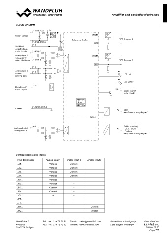
BLOCK DIAGRAM
X1-1/X1-A/X1-1
+ DC U
Supply voltage DC PWM I
- Microcontroller Solenoid A
X1-2/X1-B/X1-3 A/D
X1-3
Stabilised
output voltage LED
green
(only 12-pole) X1-4/X1-D
+
Analog input 1 + - A PWM U
voltage (only - I
without fieldbus) X1-5/X1-E Solenoid B
A/D
X1-6
+
Analog input 2 X1-7 + - D
current - LED red
(only 12-pole)
LED yellow
X1-10
Digital input 1
(only 12-pole) X1-11
Digital output 1
(only 12-pole)
FEPROM
RAM
EEPROM
X1-12/X1-G/X1-4
Chassis
X2 USB
see „Connector wiring diagram“
Option
X4-2 Fieldbus (Option)
(only controller) + A X3 • CAN / S1939
Analog input 3 + - • Profibus
D see „Connector wiring diagram“
Configuration analog inputs
Type designation Analog input 1 Analog input 2 Analog input 3
..A1.. Voltage Current
..A2.. Voltage Current
..A3.. Voltage Current
..A4.. Voltage Current
..D1.. Voltage --
..D2.. Voltage --
..D3.. Current --
..D4.. Current --
..C1.. -- --
..P1.. -- --
..J1.. -- --
..R1.. Current
..R2.. Voltage
Wandfluh AG Tel. +41 33 672 72 72 E-mail: [email protected] Illustrations not obligatory Data sheet no.
Postfach Fax +41 33 672 72 12 Internet: www.wandfluh.com Data subject to change 1.13-76E 5/10
CH-3714 Frutigen Edition 21 20
Page 725