Page 370 - Softbound_Edition_19_en
P. 370

Proportional spool valve
                                                                                     Proportional spool valve                                                                                                     Proportional spool valve


       DIMENSIONS                                                                                                                  SURFACE TREATMENT                                    SEALING MATERIAL
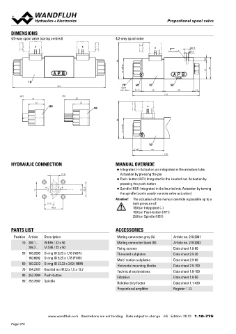
       4/3-way spool valve (spring centred)                4/2-way spool valve                                                     Standard:                                            NBR or FKM (Viton) as standard, choice in the type code
                                                                                                                                   -The valve body is painted with a two component paint
                   A                      B                                    A                    9.5                            -The armature tube, the slip-on coil and the plug screw are zinc-ni-
                                                                                      MD=5.2Nm     5.2                             ckel coated

                                                              83                                          8                        Optionally (K8):
                                                               45                                           49                     -All external parts are zinc-nickel coated
                                                                W =                                       41                       ISO 9227 (800 h) salt spray test

               10
                               210                             70    60     10         50
                                                              MD= 5Nm   21    50           68       13
                                                                                     152                                           INSTALLATION NOTES                                   STANDARDS
           HF1                  HS1
                  51                    57
                    37                    37                                                                                        Mounting type      Flange mounting                   Mounting interface  ISO 4401-03
                          80                    90                         A                                                                           4 fixing holes for                Solenoids           DIN VDE 0580
                                                                                                                                                       socket head screws M5 x 50        Connection execution D  EN 175301 – 803
                                                                                                                                    Mounting position  Any, preferably horizontal        Protection class    EN 60 529
                                                              86                                                                    Tightening torque  Fixing screws M  = 5,2 Nm (screw   Contamination efficiency  ISO 4406
                                                                                                                                                                   D
                                                               45                                                                                      quality 8.8, zinc coated)

                                                                M =                                                                                    M  = 5 Nm knurled nut
                                                                                                                                                        D
                                                                                                                                   Note!    The length of the fixing screw depends on the base
                                                                            10                                                              material of the connection element.
                                                                      18      53
                                                                                     152

       HYDRAULIC CONNECTION                                MANUAL OVERRIDE
                                                            ◆  Integrated (–) Actuation pin integrated in the armature tube.
                                 17.8                         Actuation by pressing the pin
                            T                               ◆  Push-button (HF1) Integrated in the knurled nut. Actuation by
                                                              pressing the push-button
                        A       B                             Spindle (HS1) Integrated in the knurled nut. Actuation by turning
                    31                     21    32.5       ◆
                                                              the spindle (continuously variable valve actuation)
                            P                              Attention!  The actuation of the manual override is possible up to a
                          21.5                                      tank pressure of:
                            40.5                                    160 bar Integrated (–)
                                                                    160 bar Push-button (HF1)
                                                                    250 bar Spindle (HS1)


       PARTS LIST                                          ACCESSORIES
        Position Article  Description                       Mating connector grey (A)    Article no. 219.2001
            10 206.1...  W.E45 / 23 x 50                    Mating connector black (B)   Article no. 219.2002
               206.7...  M.S45 / 23 x 50                    Fixing screws                Data sheet 1.0-60
            50 160.2093  O-ring ID 9,25 x 1,78 (NBR)        Threaded subplates           Data sheet 2.9-30
               160.6092  O-ring ID 9,25 x 1,78 (FKM)
                                                            Multi-station subplates      Data sheet 2.9-60
            60 160.2222  O-ring ID 22,22 x 2,62 (NBR)       Horizontal mounting blocks   Data sheet 2.9-100
            70 154.2701  Knurled nut M23 x 1,5 x 19,7
                                                            Technical explanations       Data sheet 1.0-100
            80 253.7004  Push-button                        Filtration                   Data sheet 1.0-50
            90 253.7002  Spindle
                                                            Relative duty factor         Data sheet 1.1-430
                                                            Proportional amplifier       Register 1.13


                                                                                                                                                                                        Wandfluh AG  Postfach  CH-3714 Frutigen
                                                                                                                                                                                        Tel. +41 33 672 72 72  Fax +41 33 672 72 12  [email protected]

                         www.wandfluh.com  Illustrations are not binding  Data subject to change  4/5  Edition: 20 23  1.10-77 E                      www.wandfluh.com  Illustrations are not binding  Data subject to change  5/5  Edition: 20 23  1.10-77 E
       Page 370
   365   366   367   368   369   370   371   372   373   374   375