Page 390 - Softbound_Edition_19_en
P. 390

Proportional spool valve
                                                                                     Proportional spool valve                                                                                                     Proportional spool valve


       DIMENSIONS                                                                                                                  Proportional spool valve stainless
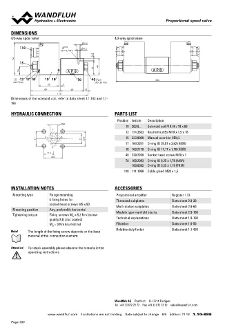
       4/2-way spool valve                                 4/3-way spool valve                                                     Flange construction                                  NG6
                                             9.5                                                                                      Q  = 30 l/min                                     ISO 4401-03
           110                               5.2                                                                                    ◆  max
                                MD= 5.2Nm                                                                                           ◆  3 volume flow levels                             x II 2 G Ex db IIC T6, T4
                                                  8                                                                                 ◆  Q N max  = 20 l/min                              x II 2 D Ex tb III C T80 °C, T130 °C
         94                                                                                                                         ◆  p  = 350 bar                                     x I M2 Ex db I Mb
           15                                                                                                                          max                                              Class I Division 1
                                                  41    49                                                                                                                              Class I Zone 1
            24
           12 17 18     10 18           70      40                               246
        MD=9Nm                                   MD=50 Nm
                          60      5
                        89            68     13                                                                                    DESCRIPTION                                          APPLICATION
                               170                                                                                                 Direct  operated  proportional  spool  valve  with  4  connections  in   These valves are suitable for applications in explosion-hazard areas,
       Dimensions of the solenoid coil, refer to data sheet 1.1-183 and 1.1-                                                       5-chamber system. Precise spool fit, low leakage, long service life   open cast and also in mines. The stainless execution is especially
       184                                                                                                                         time. Proportional to the solenoid current, the spool stroke, the spool   suitable for the use in wet and salty environment. Proportional spool
                                                                                                                                   opening and the valve volume flow increase. The pressure tight en-  valves are perfectly suitable for demanding tasks due to the high re-
       HYDRAULIC CONNECTION                                PARTS LIST                                                              capsulated Ex-protection solenoid coil prevents an explosion on the   solution, large volume flow and low hysteresis. The applications are
                                                             Position Article  Description                                         inside penetrating to the outside as well as an ignitable surface tem-  in the industrial as well as in the mobile hydraulics for the smooth


                                 17.8                                                                                              perature.                                            control of hydraulic actuations.
                                                                 10 263.6...  Solenoid coil MK.45 / 18 x 60
                            T
                                                                 12 154.2603  Knurled nut Ex M18 x 1,5 x 18
                        A       B                                15 253.8000  Manual override HB4,5
                    31                     21    32.5
                                                                 17 160.2251  O-ring ID 25,07 x 2,62 (NBR)
                            P                                    18 160.2170  O-ring ID 17,17 x 1,78 (NBR)                         CERTIFICATES                                         ACTUATION
                          21.5                                   40 239.2209  Socket head screw M20 x 1                                          Surface   Mining  Standard   M248       Actuation          Proportional solenoid, wet pin push
                            40.5                                                                                                                                     -25 °C   Electronic                    type, pressure tight
                                                                 70 160.2093  O-ring ID 9,25 x 1,78 (NBR)                                                            to…                 Execution          MKY45 / 18x60 (data sheet 1.1-183)
                                                                    160.6092  O-ring ID 9,25 x 1,78 (FKM)                           ATEX            x        x        x         x                           MKU45 / 18x60 (data sheet 1.1-184)
                                                                110 111.1080  Cable gland M20 x 1,5                                                                                      Connection         Cable gland for cable Ø 6,5…14 mm
                                                                                                                                    IECEx           x        x        x         x
                                                                                                                                    CCC             x        x        x         x       Attention!  The UL execution is always supplied without cable
                                                                                                                                    EAC             x        x        x         x                gland
       INSTALLATION NOTES                                  ACCESSORIES
                                                                                                                                    Australia       x        x        x
       Mounting type      Flange mounting                   Proportional amplifier       Register 1.13                              MA                       x        x         x
                          4 fixing holes for                Threaded subplates           Data sheet 2.9-30                          UL / CSA        x                 x
                          socket head screws M5 x 50        Multi-station subplates      Data sheet 2.9-60
       Mounting position  Any, preferably horizontal        Module type manifold blocks  Data sheet 2.9-100                        The certificates can be found on www.wandfluh.com
       Tightening torque  Fixing screws M  = 5,2 Nm (screw
                                      D
                          quality 8.8, zinc coated)         Technical explanations       Data sheet 1.0-100                        SYMBOL

                          M  = 9 Nm knurled nut             Filtration                   Data sheet 1.0-50                         Symmetrical control
                            D
                                                            Relative duty factor         Data sheet 1.1-430
       Note!   The length of the fixing screw depends on the base                                                                                 ACB-S                                AC1-S                       CB2-S
               material of the connection element.
                                                                                                                                                   A  B                                   A  B                   A  B
       Attention!  For stack assembly please observe the remarks in the                                                                      a      0     b                         a                                   b
               operating instructions                                                                                                a                              b       a                     b        a                      b
                                                                                                                                                   P  T                                   P  T                   P  T

                                                                                                                                   Meter-in control
                                                                                                                                                  ADB-V                                AD1-V                       DB2-V

                                                                                                                                                   A  B                                   A  B                   A  B
                                                                                                                                             a            b                         a                                   b
                                                                                                                                     a                              b       a                     b        a                      b
                                                                                                                                                   P  T                                   P  T                   P  T
                                                           Wandfluh AG  Postfach  CH-3714 Frutigen
                                                           Tel. +41 33 672 72 72  Fax +41 33 672 72 12  [email protected]

                         www.wandfluh.com  Illustrations are not binding  Data subject to change  6/6  Edition: 21 18  1.10-88 E                    www.wandfluh.com  Illustrations are not binding  Data subject to change  1/6  Edition: 21 18  1.10-88S E
       Page 390
   385   386   387   388   389   390   391   392   393   394   395