
Page 385 - Softbound_Edition_19_en
P. 385
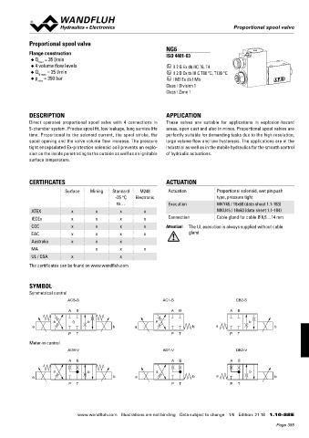
Proportional spool valve
 Proportional spool valves                                                                 Proportional spool valve


 DIMENSIONS  Proportional spool valve                            NG6
 With analog interface  2  3  4  NOTE!  6  7  8  Flange construction
 1
 5
 Amplifier and controller  The cable connector is not part of the delivery. The di-  ISO 4401-03
 1  1  2  2  3  3  4  4  5  5  6  6  7  7  8  8  ◆  Q  = 35 l/min
                max
 mensions refer to those of the cable connector in the
 chapter «Accessories».  ◆  4 volume flow levels                 x II 2 G Ex db IIC T6, T4
 40  40 21,22 21, 22  20, 30  ◆  Q   = 25 l/min                  x II 2 D Ex tb III C T80 °C, T130 °C
 20,30
                N max
 21,22
 40  21,22  40  20,30  20,30   p  = 350 bar
 A
 X2         A ◆  max                                             x I M2 Ex db I Mb
 X2  17.8
 A  A  A        A                                                Class I Division 1
 X2  X2
 X1  X1  Ø 9.5     9.5   T                                       Class I Zone 1
 X1  X1 X4     9.5        5.2  9.5   MD=5.2Nm
  112   111.4  X4     5.2   7  MD=5.2Nm     5.2   MD=5.2Nm  A  B
 X4  X4
  112    112   Ø 5.2   8   31  21  32.5  DESCRIPTION             APPLICATION
 45   45   8    8    49   Direct  operated  proportional  spool  valve  with  4  connections  in   These  valves  are  suitable  for  applications  in  explosion-hazard
            B
 B   41     5-chamber system. Precise spool fit, low leakage, long service life   areas, open cast and also in mines. Proportional spool valves are
 45   45      49    49   P
                B
 B  B   41    41   B  time.  Proportional  to  the  solenoid  current,  the  spool  stroke,  the   perfectly suitable for demanding tasks due to the high resolution,
       21.5  19
 55  55  107.5 10  60  68  50  T  40.5  spool opening and the valve volume flow increase. The pressure   large volume flow and low hysteresis. The applications are in the
 60
 MD= 5.2Nm  50  MD=5.2Nm  tight encapsulated Ex-protection solenoid coil prevents an explo-  industrial as well as in the mobile hydraulics for the smooth control
 55  10  55   108  60 10 200.8  60 50  68    15   50  sion on the inside penetrating to the outside as well as an ignitable   of hydraulic actuations.


 MD= 5.2Nm  MD= 5.2Nm   201   MD=5.2Nm  MD=5.2Nm


  108    108    68    15    68    15   surface temperature.
  201    201
 With fieldbus interface  With fieldbus interface
 C  X2      C
 Amplifier  Controller
 C  C  X1  C  CERTIFICATES                                       ACTUATION
                C
 X2  X2  X2
 50  X2                   Surface   Mining  Standard   M248       Actuation          Proportional solenoid, wet pin push
 50
 X2  X1  X2 X2  X1  X1  X3  X1               -25 °C   Electronic                     type, pressure tight
 X1
 X1  X1  X3  X3                               to…                 Execution          MKY45 / 18x60 (data sheet 1.1-183)
 X3  Ø 9.5   130   X3  X4  Ø 9.5
  112   X3   ATEX            x        x        x        x                            MKU45 / 18x60 (data sheet 1.1-184)
 X3  X3  7   130   X4   130   X4  X4  7  IECEx  x  x  x  x        Connection         Cable gland for cable Ø 6,5…14 mm
  112   D   112   111.4  129.4  D
             CCC             x        x        x        x        Attention!  The UL execution is always supplied without cable
 45          EAC             x        x        x        x                 gland
 D  D  Ø 5.2  D  D
 45  Ø 5.2
             Australia       x        x        x
 10
 10          MA                       x        x        x
  108
 107.5  68  86   108   68  UL / CSA  x         x
 10  10   196   10  10   196
  108    108   196   108   196   108   The certificates can be found on www.wandfluh.com
                Gezeichnet  06.03.2014  DWI
 E                 Geprüft  26.08.2016  JG  E
  196    196    196                  196   Freigegeben  26.08.2016  TK
 Rev.  Datum  Name Änderungsnr.  Änderungsbeschrieb  M 1:1.1  Serie freigegeben
         Gewicht
 Ersetzt durch:


 Gezeichnet
         2.771 kg


                Prop. Magnet-Schieberventil NG6 06.03.2014  DWI Ersatz für:  Gezeichnet  06.03.2014  DWI
 E
 E  E                                Geprüft  26.08.2016  JG Dok.-Nr.  Geprüft  26.08.2016  JG  E
         Format
    0150038

          A2

               WDRFA06           Freigegeben  26.08.2016  TK  Freigegeben  26.08.2016  TK
            SYMBOL
 Rev.  Datum  Name Änderungsnr.  Änderungsbeschrieb Datum  Name Änderungsnr.  Änderungsbeschrieb  M 1:1.1  Serie freigegeben  M 1:1.1  Serie freigegeben
 Rev.
 Dokument darf ohne schriftliche Einwilligung weder kopiert, Gewicht Art.-Nr.  Ersetzt durch:   Revision  Gewicht
 Ersetzt durch:
 verwertet noch an Dritte weitergegeben werden.
 Prop. Magnet-Schieberventil NG6 2.771 kg
 Ersatz für:
  Ersatz für:
 Prop. Magnet-Schieberventil NG6 Zuwiderhandlung ist strafbar und wird gerichtlich verfolgt.  DB 1.10-83  00  2.771 kg
             Format
  Dok.-Nr.
 Format
 1  2  3  4  5  Dok.-Nr.  C:\00_Wandfluh\Verkauf\Dokumentation\Reg1.10\0150038  Blatt 1 von 1  Symmetrical control
 WDRFA06  WDRFA06  0150038  A2  0150038  A2
 Dokument darf ohne schriftliche Einwilligung weder kopiert,
 Dokument darf ohne schriftliche Einwilligung weder kopiert,  Art.-Nr.  Revision  Art.-Nr.  Revision
 DB 1.10-83
 verwertet noch an Dritte weitergegeben werden.  verwertet noch an Dritte weitergegeben werden. 00  DB 1.10-83  00  ACB-S  AC1-S  CB2-S
 Zuwiderhandlung ist strafbar und wird gerichtlich verfolgt.
 Zuwiderhandlung ist strafbar und wird gerichtlich verfolgt.
 PARTS LIST  ACCESSORIES
 1  1  2  2  3  3  4  4  5  5  C:\00_Wandfluh\Verkauf\Dokumentation\Reg1.10\0150038  C:\00_Wandfluh\Verkauf\Dokumentation\Reg1.10\0150038  Blatt 1 von 1
 Blatt 1 von 1
 •  Set-up software   see start-up  A  B                           A  B                   A  B
 Position  Article  Description
 •  Cable to adjust the settings through interface USB
 20  062.0102  Cover    (from plug type A to Mini B, 3 m)    article no. 219.2896   a  0  b  a  a  b
 21  223.1317  Dummy plug M16x1,5  •  Cable connector for analog interface:  a  b  a  b                    b
 22  160.6131  O-ring ID 13,00x1,5    – straight, soldering contact    article no. 219.2330  P  T  P  T  P  T
   – 90°, soldering contact
 article no. 219.2331
 30  072.0021  Gasket 33x2x59,9x2    Recommended cable size:       Meter-in control
 40  208.0100  Socket head cap screw M4x10    – Outer diameter 9…10,5 mm  ADB-V  AD1-V      DB2-V
 50  246.2117  Socket head cap screw M5x16 DIN 912    – Single wire max. 1 mm 2
   – Recommended wire size:
 55  246.2190  Socket head cap screw M5x90 DIN 912      0…25 m = 0,75 mm  (AWG18)  A  B  A  B  A  B
 2
 60  160.2093  O-ring ID 9,25x1,78      25…50 m = 1 mm  (AWG17)
 2
                      a            b                         a                                   b
             a                               b       a                     b        a                      b
 Technical explanation see data sheet 1.0-100  P  T                P  T                   P  T

 Wandfluh AG   Tel.  +41 33 672 72 72   E-mail:  [email protected]   Illustrations not obligatory   Data sheet no.
 Postfach   Fax  +41 33 672 72 12   Internet:  www.wandfluh.com   Data subject to change   1.10-83E 4/4  www.wandfluh.com  Illustrations are not binding  Data subject to change  1/6  Edition: 21 18  1.10-88 E
 CH-3714 Frutigen     Edition 14 11
                                                                                                            Page 385