
Page 383 - Softbound_Edition_19_en
P. 383
40
21, 22
X2
X1
Ø 9.5
T
X4
111.4
45
Ø 5.2
P
21.5
55
68
107.5
40.5
200.8
50
X2
X1
Ø 9.5
Ø 9.5
X3
7
111.4
X4
7
45
68
107.5 20, 30 60 Ø 5.2 7 50 T 129.4 45 50 31 X3 X1 A X2 86 17.8 19 B Ø 5.2 21 32.5
68
196 196
Proportional spool valve
Proportional spool valves Proportional spool valves
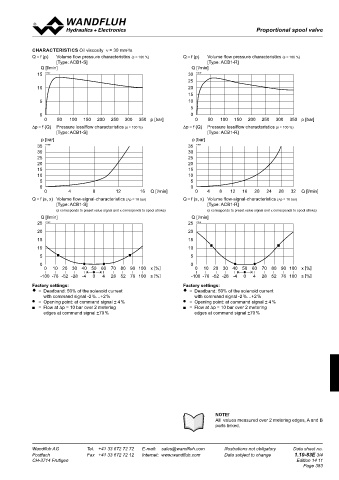
TYPE CHARTS / DESIGNATIONS OF SYMBOLS START-UP CHARACTERISTICS Oil viscosity ν = 30 mm /s
2
Normally there is no need to adjust settings by the customer. The con- Q = f (p) Volume flow pressure characteristics (s = 100 %) Q = f (p) Volume flow pressure characteristics (s = 100 %)
nectors have to be wired according to the chapter «Connector wiring [Type: ACB1-S] [Type: ACB1-R]
ACB1 - S diagram». Q [l/min] Q [l/min]
S = Symmetrical control mode Controllers will be supplied configurated as amplifiers. Switching into 15 K1157 30 K1159
controller mode and setting of the adjustments of the controller must 25
be done by the customer using the set-up software (USB interface, Mini B).
10 20
Additional information can be found on our website: 15
ACB1 - R «www.wandfluh.com» 5 10
R = Meter-out control mode Free-of-charge download of the «PASO»-software and the instruction 5
manual for the «DSV» hydraulic valves as well as the operation instruc- 0
tion CANopen protocol with device profile DSP-408 for «DSV». 0
0 50 100 150 200 250 300 350 p [bar] 0 50 100 150 200 250 300 350 p [bar]
∆p = f (Q) Pressure loss/flow characteristics (s = 100 %) ∆p = f (Q) Pressure loss/flow characteristics (s = 100 %)
HYDRAULIC SPECIFICATIONS CONNECTOR WIRING DIAGRAM [Type: ACB1-S] [Type: ACB1-R]
Fluid Mineral oil, other fluid on request Analog interface: p [bar] p [bar]
Contamination efficiency ISO 4406:1999, class 18/16/13
(Required filtration grade β 6…10 ≥ 75) Device receptacle (male) X1 35 K1160 35 K1161
refer to data sheet 1.0-50/2 1 = Supply voltage + 30 30
Viscosity range 12 mm /s…320 mm /s 2 = Supply voltage 0 VDC 25 25
2
2
Fluid temperature -20…+70 °C 8 9 1 3 = Stabilised output voltage 20 20
Working pressure p max = 350 bar (connections P, A, B) 7 12 10 2 4 = Preset value voltage + 15 15
Tank pressure p max = 160 bar (connections T) 8 9 1 6 11 3 5 = Preset value voltage - 10 10
8 9
1
Nominal volume flow Q = 10 l/min,20 l/min, 7 12 10 2 5 4 6 = Preset value current + 5 5
7 12 10 2
N
Max. volume flow see characteristic 6 11 3 7 = Preset value current - 0 0
11 3
6
Leakage volume flow on request 5 4 8 = Reserved for extensions 0 4 8 12 16 Q [l/min] 0 4 8 12 16 20 24 28 32 Q [l/min]
5
4
Hysteresis < 0,4 % 9 = Reserved for extensions Q = f (s, x) Volume flow-signal-characteristics (∆p = 10 bar) Q = f (s, x) Volume flow-signal-characteristics (∆p = 10 bar)
Repeatability < 0,4 % 10 = Enable control (Digital input) [Type: ACB1-S] [Type: ACB1-R]
Jump response typically 25 ms from 10 to 90 % 2 3 11 = Error signal (Digital output)
5 12 = Chassis (s corresponds to preset value signal and x corresponds to spool stroke) (s corresponds to preset value signal and x corresponds to spool stroke)
1
2 3 8 9 4 1 2 3 Q [l/min] Q [l/min]
5 Preset value voltage (PIN 4/5) resp. current (PIN 6/7) are selected with 25 K1162 25 K1158
5
7 12 10 2
ELECTRICAL SPECIFICATIONS 1 4 set-up and diagnosis software. 1 4 20 20
11 3
6
Protection class IP 67 acc. to EN 60 529 Factory setting: Voltage (-10…+10 V), (PIN 4/5)
with suitable connector and closed 5 4 15 15
electronic housing Fieldbus interface: 10 10
Supply voltage 24 VDC Device receptacle supply (male) X1
Ramps (amplifier only) separate adjustment for up and 2 1 2 1 5 5
down for each solenoid 5 MAIN 0 0
3
4
Preset value generator preset value speed adjustable 2 1 2 3 3 4 1 1 = Supply voltage + 0 10 20 30 40 50 60 70 80 90 100 x [%] 0 10 20 30 40 50 60 70 80 90 100 x [%]
2
1
2
(controller only) 5 5 2 = Reserved for extensions 2 1
5
Parameterisation via fielbus or USB 3 4 1 4 3 4 3 = Supply voltage 0 VDC 3 4 -100 -76 -52 -28 -4 0 4 28 52 76 100 s [%] -100 -76 -52 -28 -4 0 4 28 52 76 100 s [%]
3
4
4 = Chassis
Interface USB (Mini B) for parameterisation Factory settings: Factory settings:
with «PASO» Device receptacle CANopen Device receptacle Profibus = Deadband: 50% of the solenoid current = Deadband: 50% of the solenoid current
(under the closing screw of the housing cover, (male) X3 (female) X3 with command signal -2 %…+2 % with command signal -2 %…+2 %
factory set parameters) 2 3 = Opening point: at command signal ± 4 % = Opening point: at command signal ± 4 %
Analog interface CAN PROFIBUS = Flow at ∆p = 10 bar over 2 metering = Flow at ∆p = 10 bar over 2 metering
Device receptacle (male) M23, 12-poles 1 5 4 1 = not connected 1 = VP edges at command signal ±70 % edges at command signal ±70 %
2
1
Mating connector Plug (female), M23, 12-poles 2 3 2 1 2 = not connected 2 3 2 = RxD / TxD - N
(not incl. in delivery) 5 5 3 = CAN Gnd 5 3 = DGND
3
Preset value signal: Voltage / current selected with software 4 3 4 4 = CAN High 4 1 4 4 = RxD / TxD - P
1
Fieldbus interface: 8 9 1 5 = Shield
5 = CAN Low
Device receptacle 7 12 10 2
supply (male) M12, 4-poles Parameterisation interface (USB, Mini B) X2
6
11 3
Mating connector Plug (female), M12, 4-poles Under the closing screw of the housing cover
4
5
(not incl. in delivery)
Device receptacle Feedback signal interface
CANopen (male) M12, 5-poles (acc. to DRP 303-1) 2 3
5
Mating connector Plug (female), M12, 5-poles Device receptacle Sensor (female) X4 (controller only)
(not incl. in delivery) 1 4 2 3 1 = Supply voltage (output) +
Device receptacle 5 2 = Feedback signal +
Profibus (female) M12, 5-poles, B-codiert (acc. to IEC 947-5-2) 1 4 3 = Supply voltage 0 VDC
Mating connector Plug (male), M12, 5-poles, B-codet 4 = not connected
(not incl. in delivery) 5 = stab. output voltage
Preset value signal: Fieldbus
NOTE! NOTE!
NOTE! The mating connetor and the cable to adjust the set- All values measured over 2 metering edges, A and B
Detailed electrical characteristics and description of 2 1 tings are not part of the delivery. To order the cable, ports linked.
2
1
«DSV» electronics are shown on data sheet 1.13-75. 5 look up the article no. in the chapter «Accessories».
3 4 3 4
Wandfluh AG Tel. +41 33 672 72 72 E-mail: [email protected] Illustrations not obligatory Data sheet no. Wandfluh AG Tel. +41 33 672 72 72 E-mail: [email protected] Illustrations not obligatory Data sheet no.
Postfach Fax +41 33 672 72 12 Internet: www.wandfluh.com Data subject to change 1.10-83E 2/4 Postfach Fax +41 33 672 72 12 Internet: www.wandfluh.com Data subject to change 1.10-83E 3/4
CH-3714 Frutigen Edition 14 11 CH-3714 Frutigen Edition 14 11
Page 383
2 3
5
1 4