
Page 410 - Softbound_Edition_19_en
P. 410
WDPPU08
Proportional spool valve WDPPU10
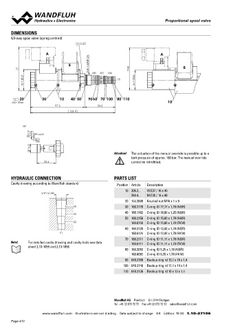
DIMENSIONS Proportional spool valve
4/3-way spool valve (spring centred) Screw-in cartridge construction 7 ⁄8 “-14 UNF
s22 Wandfluh standard
◆ direct operated
◆ Q = 28 l/min
max
A A ◆ Q N max = 18 l/min
p = 350 bar
B 3/4"-16UNF-2A ◆ max
77 74.8 B
37 4(B) 3(P) 2(A) 35 DESCRIPTION APPLICATION
1(T) Direct operated proportional spool valve in screw-in cartridge Proportional spool valves are perfectly suitable for demanding
W = M = construction. Precise spool fit, low leakage, long service life time. tasks due to the high resolution, large volume flow and low hyste-
The volume flow adjustment takes place by a Wandfluh proportio- resis. The applications are in the industry as well as in the mobile
nal solenoid. The valve works according to the pull-push principle. hydraulics for the smooth control of hydraulic actuators. Some
20 30 10 40 50 9060 70 100 80 110 With the control of the solenoids, the volume flow direction P to A examples: control of the rotor blades of wind generators, forestry
MD= 5Nm 10 or P to B can be selected. Thanks to the optimum spool form, sen - and earth moving machines, machine tools and paper production
97.2 54.2
sitive movement processes are possible. For the control, Wandfluh machines, simple position controls, robotics and fan control.
151.4
proportional amplifiers are available (see register 1.13).
HP SYMBOL
Push Symmetrical control Meter-in control
90° Lock ACB-S ADB-V
Pull
14.5 2 4 2 4
Attention! b 0 a b a
The actuation of the manual override is possible up to a
tank pressure of approx. 100 bar. The manual override
33.4 cannot be retrofitted. 3 1 3 1
TYPE CODE
HYDRAULIC CONNECTION PARTS LIST
Cavity drawing according to Wandfluh standard Position Article Description WD P PU10 - - 18 - / - #
10 206.2... W.E37 / 16 x 40 Spool valve, directly operated
3/4"-16 UNF Proportional
260.4... M.E35 / 16 x 40
20 154.2600 Knurled nut M16 x 1 x 9 Screw-in cartridge 7/8“-14 UNF
(4) 30 160.2170 O-ring ID 17,17 x 1,78 (NBR)
40 160.1162 O-ring ID 16,00 x 1,25 (NBR) Designation of symbols acc. to table
(3)
50 160.2156 O-ring ID 15,60 x 1,78 (NBR) Nominal volume flow rate Q N 18 l/min
(2) 160.6156 O-ring ID 15,60 x 1,78 (FKM)
Nominal voltage U 12 VDC G12
60 160.2120 O-ring ID 12,42 x 1,78 (NBR) N 24 VDC G24
(1) 160.6124 O-ring ID 12,42 x 1,78 (FKM) without coil X5
70 160.2111 O-ring ID 11,11 x 1,78 (NBR)
Note! For detailed cavity drawing and cavity tools see data 160.6111 O-ring ID 11,11 x 1,78 (FKM) Slip-on coil Metal housing, round W
sheet 2.13-1055 and 2.13-1056 Metal housing, square M
80 160.2093 O-ring ID 9,25 x 1,78 (NBR)
160.6092 O-ring ID 9,25 x 1,78 (FKM) Connection execution Connector socket EN 175301-803 / ISO 4400 D
Connector socket AMP Junior-Timer J
90 049.3166 Backup ring rd 13,1 x 16 x 1,4 Connector Deutsch DT04-2P G
100 049.3146 Backup ring rd 11,1 x 14 x 1,4
Sealing material NBR
110 049.3136 Backup ring rd 10 x 13 x 1,4 FKM (Viton) D1
Manual override without
with HP
Design index (subject to change)
1.10-2720
Wandfluh AG Postfach CH-3714 Frutigen
Tel. +41 33 672 72 72 Fax +41 33 672 72 12 [email protected]
www.wandfluh.com Illustrations are not binding Data subject to change 4/4 Edition: 19 34 1.10-2710 E www.wandfluh.com Illustrations are not binding Data subject to change 1/4 Edition: 19 34 1.10-2720 E
Page 410