
Page 414 - Softbound_Edition_19_en
P. 414
WDPPU10
Proportional spool valve Proportional spool valve
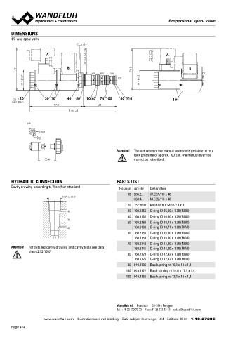
DIMENSIONS Proportional spool valve with integrated
4/3-way spool valve electronics NG4-Mini
s24 Flange construction Wandfluh standard
7/8"-14UNF-2A ◆ Q max = 12 l/min
A A ◆ direct operated
Q = 20 l/min
◆
N max
max
77 B 74.8 B ◆ p = 350 bar
4(B) 3(P) 2(A)
37 1(T) 35
W = M = DESCRIPTION APPLICATION
Direct operated proportional spool valve with 4 connections in
Proportional spool valves are perfectly suitable for demanding
5-chamber system with integrated electronics. The Plug & Play tasks due to the high resolution, large volume flow and low hyste-
valves are factory set and adjusted and have therefore a high resis. The applications are in the industry as well as in the mobile
20 30 10 40 50 90 60 70 100 80 110 10
MD= 5Nm valve-to-valve reproducibility. With protection class IP67 for the hydraulics for the smooth control of hydraulic actuators. Some
97.2 62 electronics, these valves are suitable for harsh environmental examples: control of the rotor blades of wind generators, forestry
159.2 conditions. Proportional to the electronically transmitted command and earth moving machines, machine tools and paper production
value, the spool stroke, the spool opening and the valve volume flow machines, simple position controls, robotics and fan control.
increase. The control takes place via an analogue interface or a Miniature values are used where both, reduced dimensions and
HP fieldbus interface (CANopen, J1939 or Profibus DP). The paramete- weight are important.
Push risation takes place by means of the free of cost parameterisation Note! „PASO” is a Windows programm in the flow diagram
90° Lock and diagnostics software «PASO» or via fieldbus interface. The style, which enables the intuitive adjustment and storing
Pull USB parameterisation interface is accessible through a screw of all variable parameters. The data remain saved in
14.5 plug. As an option, these valves are available with integrated case of a power failure and can also be reproduced and
Attention! The actuation of the manual override is possible up to a controller. As feedback value generators sensors with voltage or transferred to other DSV.
tank pressure of approx. 100 bar. The manual override current output can be connected directly. The available controller
33.4 cannot be retrofitted. structures are optimised for applications with hydraulic actuations.
SYMBOL
HYDRAULIC CONNECTION PARTS LIST Symmetrical control
Cavity drawing according to Wandfluh standard Position Article Description ACB-S AC1-S CB2-S
A B A B A B
10 206.2... W.E37 / 16 x 40
7/8"-14 UNF
260.4... M.E35 / 16 x 40 a 0 b a b
a b a b
20 157.2600 Knurled nut M 16 x 1 x 9
P T P T P T
(4) 30 160.2156 O-ring ID 15,60 x 1,78 (NBR) Meter-in control
40 160.1162 O-ring ID 16,00 x 1,25 (NBR)
(3) ADB-V AD1-V DB2-V
50 160.2188 O-ring ID 18,77 x 1,78 (NBR)
(2) 160.6188 O-ring ID 18,77 x 1,78 (FKM) A B A B A B
60 160.2156 O-ring ID 15,60 x 1,78 (NBR) a 0 b a b
(1) 160.6156 O-ring ID 15,60 x 1,78 (FKM) a b a b
P T P T P T
70 160.2140 O-ring ID 14,00 x 1,78 (NBR)
Attention! For detailed cavity drawing and cavity tools see data 160.6141 O-ring ID 14,00 x 1,78 (FKM)
sheet 2.13-1057
80 160.2120 O-ring ID 12,42 x 1,78 (NBR)
160.6124 O-ring ID 12,42 x 1,78 (FKM) ELECTRICAL SPECIFICATIONS ACTUATION
90 049.3196 Backup ring rd 16,1 x 19 x 1,4 Protection class IP67 with suitable mating connector and Actuation Proportional solenoid, wet pin push
100 049.3177 Back-up ring rd 14,6 x 17,5 x 1,4 closed housing cover type, pressure tight
110 049.3166 Backup ring rd 13,1 x 16 x 1,4 Ramps Adjustable Connection Via device receptacle
Parameterisation Via fieldbus or USB
Supply voltage 12 VDC, 24 VDC
Note! Exact electrical specifications and detailed description
of «DSV» electronics can be found on data sheet
1.13-76.
Wandfluh AG Postfach CH-3714 Frutigen
Tel. +41 33 672 72 72 Fax +41 33 672 72 12 [email protected]
www.wandfluh.com Illustrations are not binding Data subject to change 4/4 Edition: 19 34 1.10-2720 E www.wandfluh.com Illustrations are not binding Data subject to change 1/6 Edition: 19 30 1.10-3240 E
Page 414