Page 530 - Softbound_Edition_19_en
P. 530

Poppet valve
                                                                                       Poppet valve cartridge                                                                                                                Poppet valve


       GENERAL SPECIFICATIONS                              ACTUATION                                                               PERFORMANCE SPECIFICATIONS
                                                                                                                                                    2
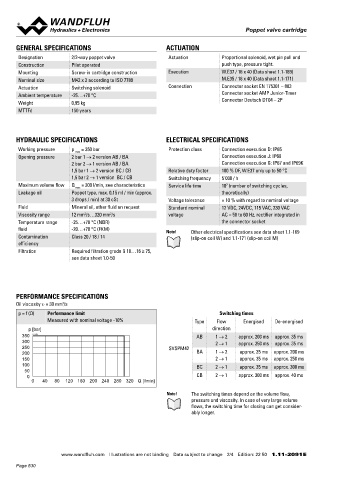
       Designation        2/2-way poppet valve              Actuation          Proportional solenoid, wet pin pull and             Oil viscosity u = 30 mm /s
       Construction       Pilot operated                                       push type, pressure tight.                           ∆p = f (Q)  Pressure drop volume flow characteristics  ∆p = f (Q)  Pressure drop volume flow characteristics
       Mounting           Screw-in cartridge construction   Execution          W.E37 / 16 x 40 (Data sheet 1.1-169)                    p [bar]                                              p [bar]
       Nominal size       M42 x 2 according to ISO 7789                        M.E35 / 16 x 40 (Data sheet 1.1-171)                   14  K1148                                            10  K1148                            2 → 1; BC / CB
       Actuation          Switching solenoid                Connection         Connector socket EN 175301 – 803                       12                                   1 → 2; AB / BA  8,3                                  1 → 2; BC / CB
                                                                                                                                                                           2 → 1; AB / BA
       Ambient temperature  -25…+70 °C                                         Connector socket AMP Junior-Timer                      10                                                   6,6
       Weight             0,95 kg                                              Connector Deutsch DT04 – 2P                            8 6                                                  5,0
       MTTFd              150 years                                                                                                   4                                                    3,4
                                                                                                                                      2                                                    1,7
                                                                                                                                      0                                                     0
                                                                                                                                        0    50   100   150   200   250  300  Q [l/min]       0    50   100   150  200   250   300 Q [l/min]

       HYDRAULIC SPECIFICATIONS                            ELECTRICAL SPECIFICATIONS                                               Attention!  Measured with cavity according to data sheet 2.13-1059
                                                                                                                                            (annular groove)
       Working pressure   p   = 350 bar                     Protection class   Connection execution D: IP65
                           max
       Opening pressure   2 bar 1 → 2 version AB / BA                          Connection execution J: IP66
                          2 bar 2 → 1 version AB / BA                          Connection execution G: IP67 and IP69K              DIMENSIONS                                           HYDRAULIC CONNECTION
                          1,5 bar 1 → 2 version BC / CB     Relative duty factor  100 % DF, W.E37 only up to 50 °C                                                                      Cavity drawing according to ISO 7789–42–01–0–07
                          1,5 bar 2 → 1 version  BC / CB    Switching frequency  5'000 / h
       Maximum volume flow  Q  max  = 300 l/min, see characteristics  Service life time  10  (number of switching cycles,                                          s46                                         M42x2
                                                                                7
       Leakage oil        Poppet type, max. 0,15 ml / min (approx.             theoretically)                                                                          M42x2     60
                          3 drops / min) at 30 cSt          Voltage tolerance  ± 10 % with regard to nominal voltage                        77                               (2)
       Fluid              Mineral oil, other fluid on request  Standard nominal   12 VDC, 24VDC, 115 VAC, 230 VAC
                                        2
                               2
       Viscosity range    12 mm /s…320 mm /s                voltage            AC = 50 to 60 Hz, rectifier integrated in                     37                                    (1)                                 (2)
       Temperature range   -25…+70 °C (NBR)                                    the connector socket                                           W =
       fluid              -20…+70 °C (FKM)                 Note!    Other electrical specifications see data sheet 1.1-169
       Contamination      Class 20 / 18 / 14                        (slip-on coil W) and 1.1-171 (slip-on coil M)                      15     12  16  10  19         40  13  30                                    (1)
       efficiency                                                                                                                   M D=9.5Nm  M D= 5Nm
                                                                                                                                                           75              56
       Filtration         Required filtration grade ß 10…16 ≥ 75,                                                                                                135                    Note!    Detailed cavity drawing refer to data sheet 2.13-1050
                          see data sheet 1.0-50


                                                                                                                                            75
       PERFORMANCE SPECIFICATIONS                                                                                                            35                                         PARTS LIST
       Oil viscosity u = 30 mm /s                                                                                                             M =                                        Position Article  Description
                       2
       p = f (Q)  Performance limit                                           Switching times                                                                                                 10 206.2...  W.E37 / 16 x 40
                  Measured with nominal voltage -10%                 Type    Flow      Energised  De-energised                                       10                                          260.4...  M.E35 / 16 x 40
           p [bar]                                                          direction                                                                                                         12 154.2600  Knurled nut M16 x 1 x 9
         350  K1149                                                   AB     1 → 2   approx. 200 ms  approx. 35 ms                 HYDRAULIC CONNECTION                                       13 212.0013  Plastic disc rd 7 x 1,5
         300                                                                 2 → 1   approx. 250 ms  approx. 35 ms                 Cavity  drawing  according  to  ISO  7789–42–01–0–07  (with  annular   15 239.2033  Screw plug HB0 (incl. seal)
         250                                                SVSPM42                                                                groove) recommended for minimum delta p values

         200                                                          BA     1 → 2   approx. 35 ms  approx. 200 ms                                                                             - 251.3017  Seal kit SV.PM42 NBR
         150                                                                 2 → 1   approx. 35 ms  approx. 250 ms                                       M42 x 2                                 251.3041  Seal kit SV.PM42 D1
         100                                                          BC     2 → 1   approx. 35 ms  approx. 300 ms                                                                               251.3020  Seal kit SV.PM42 Z604
          50
           0                                                          CB     2 → 1   approx. 300 ms  approx. 40 ms
            0   40   80  120  160 200 240 280 320  Q [l/min]
                                                                                                                                                                   (2)                                                            Seal kit consisting of
                                                                                                                                                                                                      16    O-ring         ID 15,60 x 1,78
                                                            Note!   The switching times depend on the volume flow,
                                                                    pressure and viscosity. In case of very large volume                                                                              19    O-ring         ID 26,00 x 1,00
                                                                    flows, the switching time for closing can get consider-                                                                           30    O-ring         ID 32,99 x 2,62
                                                                    ably longer.                                                                                                                      40    O-ring         ID 37,77 x 2,62
                                                                                                                                                             (1)                                      60    Back. ring  PTFE rd 33,5 x 38 x 1,4

                                                                                                                                   Note!    Detailed cavity drawing refer to data sheet 2.13-1059


                       www.wandfluh.com  Illustrations are not binding  Data subject to change  2/4  Edition: 22 50  1.11-2091 E                   www.wandfluh.com  Illustrations are not binding  Data subject to change  3/4  Edition: 22 50  1.11-2091 E
       Page 530
   525   526   527   528   529   530   531   532   533   534   535