Page 534 - Softbound_Edition_19_en
P. 534

Poppet valve
                                                                                       Poppet valve cartridge                                                                                                                Poppet valve


       TYPE CODE                                                                                                                   ELECTRICAL SPECIFICATIONS                            STANDARDS
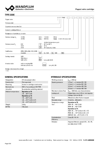
                                                                   S  V  Y  PM42  -     -     /        -        #                   Protection class   IP65 / 66 / 67                    Cartridge cavity   ISO 7789
       Poppet valve                                                                                                                 Relative duty factor  100 % DF                       Explosion protection  Directive 2014 / 34 / EU (ATEX)

       Pilot operated                                                                                                               Switching frequency  5'000 / h                       Flameproof enclosure  EN / IEC / UL 60079-1, 31
                                                                                                                                    Voltage tolerance  ± 10 % with regard to nominal voltage  Cable entry   EN 60079-0, 1, 7, 15, 31
       Ex-protection execution, Exd                                                                                                 Standard nominal   12 VDC, 24VDC, 115 VAC, 230 VAC   Protection class   EN 60 529
                                                                                                                                    voltage            AC = 50 to 60 Hz ± 2 %, with built-in   Contamination   ISO 4406
       Screw-in cartridge M42 x 2
                                                                                                                                                       two-way rectifier                 efficiency
       Designation of symbols acc. to table                                                                                         Standard nominal   9 W, 15 W, 17 W
                                                                                                                                    power
       Nominal voltage U    12 VDC            G12   115 VAC    R115                                                                 Temperature class  Nominal power 9 W: T1…T6
                   N
                         24 VDC               G24   230 VAC    R230   (not for UL execution)
                                                                                                                                                       Nominal power 15 W / 17 W: T1…T4
                                                   Ambient temperature up to:
       Nominal power P    9 W                 L9   40 °C or 90 °C                                                                  Note!    Other electrical specifications see data sheet 1.1-183
                  N
                         15 W                 L15   70 °C                                                                                   and 1.1-184
                         17 W                 L17   70 °C (only UL / CSA)
       Certification     ATEX, IECEx, EAC, CCC, UKEX
                         Australia            AU   UL / CSA   UL   MA   MA                                                         PERFORMANCE SPECIFICATIONS
                                                                                                                                   Oil viscosity u = 30 mm /s
                                                                                                                                                    2
       Sealing material   NBR
                         FKM (Viton)          D1                                                                                    p = f (Q)  Performance limit                                           Switching times
                         NBR -40° C           Z604   (only with 15 W)                                                                         Measured with nominal voltage -10%                  Type    Flow     Energised  De-energised
                                                                                                                                        p [bar]                                                         direction
       Armature tube     with screw plug HB0                                                                                             K1149
                         with manual override     HB4,5   (only AB, CB)                                                              350                                                           AB    1 → 2    approx. 200 ms  approx. 35 ms
                                                                                                                                     300                                                                 2 → 1    approx. 250 ms  approx. 35 ms
       Design index (subject to change)                                                                                              250                                                 SVSPM42   BA    1 → 2    approx. 35 ms  approx. 200 ms
                                                                                                                                     200
       1.11-2092
                                                                                                                                     150                                                                 2 → 1    approx. 35 ms  approx. 250 ms
                                                                                                                                     100                                                           BC    2 → 1    approx. 35 ms  approx. 300 ms
                                                                                                                                      50
       GENERAL SPECIFICATIONS                              HYDRAULIC SPECIFICATIONS                                                    0                                                           CB    2 → 1    approx. 300 ms  approx. 40 ms
                                                                                                                                         0   40   80  120  160 200 240 280 320  Q [l/min]
       Designation        2/2-way poppet valve              Working pressure   p  = 350 bar
                                                                                max
       Construction       Pilot operated                    Opening pressure   1,5 bar 1 → 2 version BC / CB
       Mounting           Screw-in cartridge construction                      1,5 bar 2 → 1 version BC / CB                        ∆p = f (Q)  Pressure drop volume flow characteristics  ∆p = f (Q)  Pressure drop volume flow characteristics
       Nominal size       M42 x 2 according to ISO 7789                        2,0 bar 1 → 2 version AB / BA                           p [bar]                                              p [bar]
       Actuation          Ex-protection switching solenoid                     2,0 bar 2 → 1 version AB / BA                          14  K1148                            1 → 2; AB / BA  10  K1148                            2 → 1; BC / CB
       Ambient temperature  Operation as T6                 Maximum volume flow  Q  = 300 l/min, see characteristics                  12                                   2 → 1; AB / BA  8,3                                  1 → 2; BC / CB
                                                                                max
                          -25…+40 °C (L9)                   Leakage oil        Poppet type, max. 0,15 ml / min (approx.               10                                                   6,6
                          Operation as T4                                      3 drops / min) at 30 cSt                               8 6                                                  5,0
                          -25…+90 °C (L9)                   Fluid              Mineral oil, other fluid on request                    4                                                    3,4
                          -25…+70 °C (L15 / L17)            Viscosity range    12 mm /s…320 mm /s                                     2                                                    1,7
                                                                                   2
                                                                                            2
                          -40…+70 °C (L15 / L17)            Temperature range   Operation as T6                                       0  0   50   100   150   200   250  300  Q [l/min]     0  0   50   100   150  200   250   300 Q [l/min]
       Weight             2,4 kg                            fluid              NBR -25…+40 °C (L9)
       MTTFd              150 years                                            FKM -20…+40 °C (L9)
                                                                               Operation as T4                                     Note!    The switching times depend on the volume flow,   Attention!  Measured with cavity according to data sheet 2.13-1059
                                                                               NBR -25…+70 °C (L9 or L15 / L17)                             pressure and viscosity. In case of very large volume   (annular groove)
                                                                               FKM -20…+70 °C (L9 or L15 / L17)                             flows, the switching time for closing can get consider-
                                                                               NBR 872 -40…+70 °C (L15 / L17)                               ably longer.
                                                            Contamination      Class 20 / 18 / 14
                                                            efficiency
                                                            Filtration         Required filtration grade ß 10…16 ≥ 75,             SURFACE TREATMENT                                    MANUAL OVERRIDE
                                                                               see data sheet 1.0-50                                ◆  The cartridge body, the slip-on coil and the armature tube are   Screw plug (HB0), no actuation possible.
                                                                                                                                     zinc-nickel coated                                 Optionally HN (K) or HG (K) (pushing) resp. HZ (K) (pulling)
                                                                                                                                                                                        → See data sheet 1.1-311
                                                                                                                                                                                        Attention!  The manual override HZ (K) can neither be dismantled
                                                                                                                                                                                                 nor retrofitted


                       www.wandfluh.com  Illustrations are not binding  Data subject to change  2/4  Edition: 22 50  1.11-2092 E                   www.wandfluh.com  Illustrations are not binding  Data subject to change  3/4  Edition: 22 50  1.11-2092 E
       Page 534
   529   530   531   532   533   534   535   536   537   538   539