Page 536 - Softbound_Edition_19_en
P. 536

Poppet valve
                                                                                                Poppet valve                                                                                                                 Poppet valve


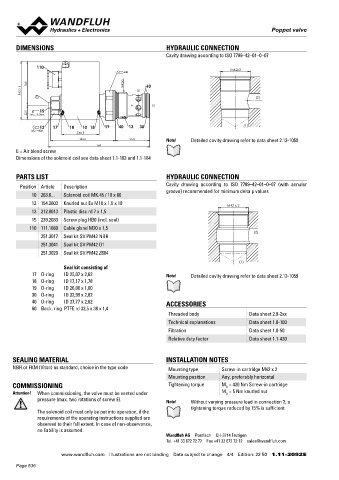
       DIMENSIONS                                          HYDRAULIC CONNECTION                                                    Solenoid operated poppet valve
                                                           Cavity drawing according to ISO 7789–42–01–0–07                         Flange construction                                  NG3-Mini
                                                                                                                                                                                        Wandfluh standard
              110                                                                                                                   ◆  2/2-, 3/2- and 3/4-way
                                             s46                                   M42x2                                            ◆  normally open and normally closed
                                                                                                                                    ◆  Q  = 6 l/min
                                                                                                                                       max
           70.8                             M42x2   60                                                                              ◆  p  = 350 bar
         93.3                                    (2)                                                                                    max
              E                                                                            (2)
                                                      (1)
               15
           22.5   M D= 9.5Nm                                                                                                       DESCRIPTION                                          APPLICATION
                                                                                                                                   Direct operated 2/2-, 3/2 and 3/4-way solenoid poppet valve in flange   Poppet valves are used where tight closing functions of the valve are
               12   17   18   10 18   19   40  13  30                                  (1)                                         construction. By means of the pressure tight switching solenoid, the   essential like leakage-free load holding, clamping or gripping. Minia-
            M D=9Nm
                             60                                                                                                    poppet valve spool is opened or closed acting against the spring. Due   ture values are used where both, reduced dimensions and weight are


                              104.2            55.8        Note!    Detailed cavity drawing refer to data sheet 2.13-1050          to the poppet spool construction with pressure compensation on both   important.
                                    164                                                                                            sides, the flow through the valve is possible in both directions. The
       E = Air bleed screw                                                                                                         seat spool guide is sealed by means of an O-ring. The metallically
       Dimensions of the solenoid coil see data sheet 1.1-183 and 1.1-184
                                                                                                                                   sealing seat closes the valve virtually leak free.

       PARTS LIST                                          HYDRAULIC CONNECTION
        Position Article  Description                      Cavity  drawing  according  to  ISO  7789–42–01–0–07  (with  annular
                                                           groove) recommended for minimum delta p values                          SYMBOL
            10 263.6...  Solenoid coil MK.45 / 18 x 60
                                                                                                                                   B.22030b                 B.22031a                    B.32030b                 B.32031a
            12 154.2603  Knurled nut Ex M18 x 1,5 x 18                           M42 x 2                                                   A                           A                       A                            A
            13 212.0013  Plastic disc rd 7 x 1,5
                                                                                                                                     a    a     b    b       a     a     b    b           a    a    b     b       a      a    b   b
            15 239.2033  Screw plug HB0 (incl. seal)
                                                                                                                                           P                           P                       P T                          P T
           110 111.1080  Cable gland M20 x 1,5
                                                                                          (2)                                      B.3403
               251.3017  Seal kit SV.PM42 NBR
                                                                                                                                               A
               251.3041  Seal kit SV.PM42 D1
                                                                                                                                           a   o   ab    b
               251.3020  Seal kit SV.PM42 Z604                                                                                       a                        b
                                                                                                                                               P T
                                                                                     (1)
                                                 Seal kit consisting of
                     17    O-ring         ID 25,07 x 2,62  Note!    Detailed cavity drawing refer to data sheet 2.13-1059
                     18    O-ring         ID 17,17 x 1,78                                                                          TYPE CODE
                     19    O-ring         ID 26,00 x 1,00                                                                           2/2 or 3/2 way execution                                                 B        2  03      -     -     #
                     30    O-ring         ID 32,99 x 2,62                                                                           3/4 way execution                                                        B      3   4  03      -     -     #
                     40    O-ring         ID 37,77 x 2,62  ACCESSORIES                                                              Mounting interface acc. to Wandfluh standard
                     60    Back. ring  PTFE rd 33,5 x 38 x 1,4
                                                            Threaded body                Data sheet 2.9-2xx                         Solenoid, Medium                 M
                                                            Technical explanations       Data sheet 1.0-100                         Solenoid, Super                   S
                                                            Filtration                   Data sheet 1.0-50                          2 way (connections)               2
                                                            Relative duty factor         Data sheet 1.1-430                         3 way (connections)               3
                                                                                                                                    2 switching positions
     SEALING MATERIAL                                      INSTALLATION NOTES                                                       4 switching positions
     NBR or FKM (Viton) as standard, choice in the type code  Mounting type    Screw-in cartridge M42 x 2                           Nominal size 3-Mini
                                                            Mounting position  Any, preferably horizontal                           Normally closed        Solenoid on A-side            1a
     COMMISSIONING                                          Tightening torque  M  = 420 Nm Screw-in cartridge                       Normally open          Solenoid on B-side            0b
                                                                                D
     Attention!  When commissioning, the valve must be vented under            M  = 5 Nm knurled nut
                                                                                D
                pressure (max. two rotations of screw E).  Note!    Without varying pressure load in connection 2, a                Nominal voltage U   N  12 VDC    G12       115 VAC   R115
                                                                                                                                                                     G24
                                                                                                                                                           24 VDC
                                                                                                                                                                               230 VAC

                                                                                                                                                                                        R230
                                                                    tightening torque reduced by 15% is sufficient
              The solenoid coil must only be put into operation, if the                                                             Sealing material       NBR
              requirements of the operating instructions supplied are                                                                                      FKM (Viton)   D1
              observed to their full extent. In case of non-observance,
              no liability is assumed.                                                                                              Design index (subject to change)
                                                           Wandfluh AG  Postfach  CH-3714 Frutigen                                  1.11-2100
                                                           Tel. +41 33 672 72 72  Fax +41 33 672 72 12  [email protected]
                       www.wandfluh.com  Illustrations are not binding  Data subject to change  4/4  Edition: 22 50  1.11-2092 E                   www.wandfluh.com  Illustrations are not binding  Data subject to change  1/4  Edition: 22 37  1.11-2100 E
       Page 536
   531   532   533   534   535   536   537   538   539   540   541