Page 538 - Softbound_Edition_19_en
P. 538

Poppet valve
                                                                                                Poppet valve                                                                                                                 Poppet valve


       GENERAL SPECIFICATIONS                              ACTUATION                                                               STANDARDS                                            ACCESSORIES
       Designation        2/2-, 3/2- and 3/4-way poppet valve  Actuation       Switching solenoid, wet pin push type,               Mounting interface  Wandfluh standard                Fixing screws               Data sheet 1.0-60
       Construction       Direct operated                                      pressure tight                                       Solenoids           DIN VDE 0580                     Threaded subplates          Data sheet 2.9-05
       Mounting           Flange construction               Execution          Medium: SIN29V (Data sheet 1.1-80)                   Connection execution D  EN 175301 – 803              Multi-station subplates     Data sheet 2.9-45
       Nominal size       NG3-Mini according to Wandfluh                       Super: SIS29V (Data sheet 1.1-85)                    Protection class    EN 60 529                        Horizontal mounting blocks  Data sheet 2.9-85
                          standard                          Connection         Connector socket EN 175301 – 803                     Contamination efficiency  ISO 4406                   Technical explanations      Data sheet 1.0-100
       Actuation          Switching solenoid
       Ambient temperature  -25…+70 °C                                                                                                                                                   Filtration                  Data sheet 1.0-50
       Weight             0,46 kg (2/2- and 3/2-way)       COMMISSIONING                                                                                                                 Relative duty factor        Data sheet 1.1-430
                          0,72 kg (3/4-way)                Attention!    When commissioning, the valve must be vented under
                                                                    pressure (max. two rotations of screw E).
       MTTFd              150 years                                                                                                INSTALLATION NOTES                                   MANUAL OVERRIDE
                                                                                                                                    Mounting type      Flange mounting                  Screw plug (HB0), no actuation possible
                                                                                                                                                                                        Optionally: HB4,5, HN(K) or HG(K)
       ELECTRICAL SPECIFICATIONS                           HYDRAULIC SPECIFICATIONS                                                                    3 fixing holes for               → See data sheet 1.1-311
                                                                                                                                                       socket head screws M4 x 30
       Protection class   IP65                              Working pressure   Medium: p  = 125 bar                                 Mounting position  Any, preferably horizontal
                                                                                      max
       Relative duty factor  100 % DF                                          Super: p  = 350 bar                                  Tightening torque  Fixing screws M  = 2,6 Nm (quality 8.8,
                                                                                     max
       Switching frequency  15'000 / h                      Maximum volume flow  Q  = 6 l/min, see characteristic                                      zinc coated)  D                  SEALING MATERIAL
                                                                                max
       Service life time  10  (number of switching cycles,   Volume flow direction  Any (see characteristic)                                                                            NBR or FKM (Viton) as standard, choice in the type code
                            7
                          theoretically)                    Leakage oil        Poppet type, max. 0,05 ml / min (approx.            Note!    The length of the fixing screw depends on the base
       Voltage tolerance  ± 10 % with regard to nominal voltage                1 drop / min) at 30 cSt                                      material of the connection element.
       Standard nominal   12 VDC, 24VDC, 115 VAC, 230 VAC   Fluid              Mineral oil, other fluid on request
                                                                                            2
       voltage            AC = 50 to 60 Hz, rectifier integrated in   Viscosity range  12 mm /s…320 mm /s
                                                                                   2
                          the connector socket              Temperature range   -25…+70 °C (NBR)
                                                            fluid              -20…+70 °C (FKM)                                    VALVES INSTALLED
       Note!   Other electrical specifications see data sheet 1.1-80                                                               The central functioning element is the poppet valve cartridge listed below
               (Medium) and 1.1-85 (Super)                  Contamination      Class 20 / 18 / 14
                                                            efficiency                                                              Article       Description                                                       Data sheet no.
                                                            Filtration         Required filtration grade ß 10…16 ≥ 75,              2203          Solenoid poppet valve cartridge normally closed NG3               1.11-2010
                                                                               see data sheet 1.0-50
       PERFORMANCE SPECIFICATIONS
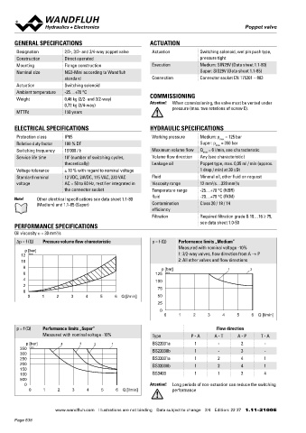
       Oil viscosity u = 30 mm /s                                                                                                  DIMENSIONS
                       2
       ∆p = f (Q)  Pressure volume flow characteristic      p = f (Q)  Performance limits „Medium”                                 3/2-; 2/2-way                                        3/2-; 2/2-way
                                                                      Measured with nominal voltage -10%                                                      30
           p [bar]                                                                                                                                                                               35
         12  K0018                                                    1: 3/2-way valves, flow direction from A → P                                      A                7.5                            B
         10                                                           2: All other valves and flow directions                                                              MD= 2.6Nm
          8                                                     p [bar]                   1       2                                                                     4.3    5.5
          6                                                  125  K0019                                                                   69
          4                                                  100                                                                           29   E                               29   30
          2                                                   75                                                                                                               24.5
          0
            0    1     2     3    4     5     6  Q [l/min]    50                                                                       20     50     10        70        40  60                            10
                                                              25                                                                    MD=9.5Nm  MD=1.2Nm   4    42    38    7   MD=1.2Nm         38
                                                               0                                                                                         93  B.22031a                             100  B.22030b
                                                                                                                                                                                                 100  B.32030b
                                                                 0     1    2     3     4    5     6  Q [l/min]                                          100  B.32031a
                                                                                                                                   E = Air bleed screw
       p = f (Q)  Performance limits „Super”                                         Flow direction                                3/4-way
                  Measured with nominal voltage -10%        Type           P - A    A - T    A - P    T - A                                       30       35
           p [bar]       4      3     2     1               BS22031a         1        -        2        -                                   A                     B
         350  K0017                                         BS22030b         1        -        3        -
         300
         250                                                BS32031a         1        2        4        1
         200                                                BS32030b         1        2        4        1
         150
         100                                                BS3403           1        1        2        4
         500
           0                                               Attention!  Long periods of non-actuation can reduce the switching             10            53
            0     1    2     3     4    5     6  Q [l/min]          performance                                                                        164


                       www.wandfluh.com  Illustrations are not binding  Data subject to change  2/4  Edition: 22 37  1.11-2100 E                   www.wandfluh.com  Illustrations are not binding  Data subject to change  3/4  Edition: 22 37  1.11-2100 E
       Page 538
   533   534   535   536   537   538   539   540   541   542   543