
Page 542 - Softbound_Edition_19_en
P. 542
Poppet valve
Poppet valve Poppet valve
GENERAL SPECIFICATIONS ACTUATION VALVES INSTALLED
Designation 2/2-, 3/2- and 3/4-way poppet valve Actuation Switching solenoid, wet pin push type, The central functioning element is the poppet valve cartridge listed below
Construction Direct operated pressure tight Article Description Data sheet no.
Mounting Flange construction Execution Medium: SIN35V (Data sheet 1.1-105) 2204 Solenoid poppet valve cartridge normally closed NG4 1.11-2020
Nominal size NG4-Mini according to Wandfluh Super: SIS35V (Data sheet 1.1-110)
standard Connection Connector socket EN 175301 – 803 DIMENSIONS
Actuation Switching solenoid 3/2-; 2/2-way 3/2-; 2/2-way
Ambient temperature -25…+70 °C 30
Weight 0,95 kg (2/2- and 3/2-way) COMMISSIONING 9.5 35
1,45 kg (3/4-way) Attention! When commissioning, the valve must be vented under A 5.5 MD=5.2Nm B
MTTFd 150 years pressure (max. two rotations of screw E). 5.5
76
E
35 35 38
32.5
ELECTRICAL SPECIFICATIONS HYDRAULIC SPECIFICATIONS
20 50 10 70 40 60 10
Protection class IP65 Working pressure Medium: p = 160 bar MD= 9.5Nm MD=2.6Nm MD= 2.6Nm 54
max
Relative duty factor 100 % DF Super: p = 350 bar 4 59 54 10 134 B.22040b
max
Switching frequency 15'000 / h Maximum volume flow Q = 15 l/min, see characteristics 124 B.22041a 134 B.32040b
max
7
Service life time 10 (number of switching cycles, Volume flow direction Any (see characteristic) E = Air bleed screw 134 B.32041a
theoretically) Leakage oil Poppet type, max. 0,05 ml / min (approx. 3/4-way
Voltage tolerance ± 10 % with regard to nominal voltage 1 drop / min) at 30 cSt
Standard nominal 12 VDC, 24VDC, 115 VAC, 230 VAC Fluid Mineral oil, other fluid on request 30 35
voltage AC = 50 to 60 Hz, rectifier integrated in Viscosity range 12 mm /s…320 mm /s A B
2
2
the connector socket Temperature range -25…+70 °C (NBR)
fluid -20…+70 °C (FKM)
Note! Other electrical specifications see data sheet 1.1-105
(Medium) and 1.1-110 (Super) Contamination Class 20 / 18 / 14
efficiency
Filtration Required filtration grade ß 10…16 ≥ 75, 10 82
see data sheet 1.0-50 221
PERFORMANCE SPECIFICATIONS
Oil viscosity u = 30 mm /s
2
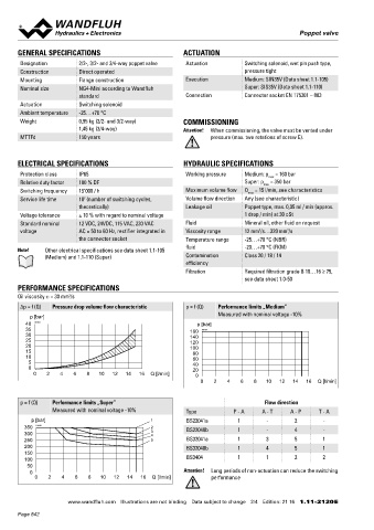
∆p = f (Q) Pressure drop volume flow characteristic p = f (Q) Performance limits „Medium” HYDRAULIC CONNECTION PARTS LIST
Measured with nominal voltage -10%
p [bar] Position Article Description
40 K0154 p [bar] 28
35 160 K0152 10 260.4... Solenoid SIN35V
30 140 14 260.5... Solenoid SIS35V
25 120
20 100 P 20 239.2033 Screw plug HB0 (incl. seal)
15 80 30 219.2001 Electric plug A (grey)
10 60 A B 14 27
5 40 35 219.2002 Electric plug B (black)
0 20 T T0
0 2 4 6 8 10 12 14 16 Q [l/min] 0 40 057.4201 Cover
0 2 4 6 8 10 12 14 16 Q [l/min] 50 246.1161 Socket head screw M4 x 60 DIN 912
60 246.1113 Socket head screw M4 x 12 DIN 912
70 160.2052 O-ring ID 5,28 x 1,78 (NBR)
p = f (Q) Performance limits „Super” Flow direction
Measured with nominal voltage -10% Type P - A A - T A - P T - A 160.6052 O-ring ID 5,28 x 1,78 (FKM)
p [bar] 1 BS22041a 1 - 2 -
350 K0153 2 BS22040b 1 - 4 - SEALING MATERIAL STANDARDS
300 3 4 NBR or FKM (Viton) as standard, choice in the type code Mounting interface Wandfluh standard
250 5 BS32041a 1 3 5 1
200 BS32040b 1 4 5 1 Solenoids DIN VDE 0580
150 Connection execution D EN 175301 – 803
100 BS3404 1 1 2 2 Protection class EN 60 529
50 Contamination efficiency ISO 4406
0 Attention! Long periods of non-actuation can reduce the switching
0 2 4 6 8 10 12 14 16 Q [l/min] performance
www.wandfluh.com Illustrations are not binding Data subject to change 2/4 Edition: 21 16 1.11-2120 E www.wandfluh.com Illustrations are not binding Data subject to change 3/4 Edition: 21 16 1.11-2120 E
Page 542