Page 544 - Softbound_Edition_19_en
P. 544
Poppet valve
Poppet valve Poppet valve
ACCESSORIES MANUAL OVERRIDE Solenoid operated poppet valve
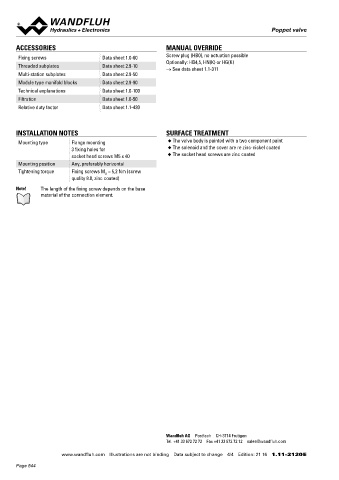
Fixing screws Data sheet 1.0-60 Screw plug (HB0), no actuation possible Flange construction NG6
Optionally: HB4,5, HN(K) or HG(K) ISO 4401-03
Threaded subplates Data sheet 2.9-10 → See data sheet 1.1-311 ◆ 2/2-, 3/2- and 3/4-way
Multi-station subplates Data sheet 2.9-50 ◆ normally open and normally closed
◆ Q = 40 l/min
Module type manifold blocks Data sheet 2.9-90 max
◆ p = 350 bar
Technical explanations Data sheet 1.0-100 max
Filtration Data sheet 1.0-50
Relative duty factor Data sheet 1.1-430 DESCRIPTION APPLICATION
Direct operated 2/2-, 3/2 and 3/4-way solenoid poppet valve in Poppet valves are used where tight closing functions of the valve
flange construction. By means of the pressure tight switching are essential like leakage-free load holding, clamping or gripping.
INSTALLATION NOTES SURFACE TREATMENT solenoid, the poppet valve spool is opened or closed acting against
the spring. Due to the poppet spool construction with pressure
Mounting type Flange mounting ◆ The valve body is painted with a two component paint compensation on both sides, the flow through the valve is possible
3 fixing holes for ◆ The solenoid and the cover are re zinc-nickel coated in both directions. The seat spool guide is sealed by means of an
socket head screws M5 x 40 ◆ The socket head screws are zinc coated O-ring. The metallically sealing seat closes the valve virtually leak
Mounting position Any, preferably horizontal free.
Tightening torque Fixing screws M = 5,2 Nm (screw
D
quality 8.8, zinc coated)
Note! The length of the fixing screw depends on the base SYMBOL
material of the connection element. A.22060b A.22061a A.32060b A.32061a
A A A A
a b a b a b a b
a b a b a b a b
P P P T P T
A.3406
A
ab
a o b
a b
P T
TYPE CODE
2/2 or 3/2 way execution A 2 06 - - #
3/4 way execution A 3 4 06 - - #
International standard interface ISO
Solenoid, Medium M
Solenoid, Super S
2 way (connections) 2
3 way (connections) 3
2 switching positions
4 switching positions
Nominal size 6
Normally closed Solenoid on A-side 1a
Normally open Solenoid on B-side 0b
Nominal voltage U N 12 VDC G12 115 VAC R115
24 VDC G24 230 VAC R230
Sealing material NBR
FKM (Viton) D1
Design index (subject to change)
Wandfluh AG Postfach CH-3714 Frutigen 1.11-2140
Tel. +41 33 672 72 72 Fax +41 33 672 72 12 [email protected]
www.wandfluh.com Illustrations are not binding Data subject to change 4/4 Edition: 21 16 1.11-2120 E www.wandfluh.com Illustrations are not binding Data subject to change 1/4 Edition: 21 16 1.11-2140 E
Page 544

