
Page 539 - Softbound_Edition_19_en
P. 539
Poppet valve
Poppet valve
STANDARDS ACCESSORIES
Mounting interface Wandfluh standard Fixing screws Data sheet 1.0-60
Solenoids DIN VDE 0580 Threaded subplates Data sheet 2.9-05
Connection execution D EN 175301 – 803 Multi-station subplates Data sheet 2.9-45
Protection class EN 60 529 Horizontal mounting blocks Data sheet 2.9-85
Contamination efficiency ISO 4406
Technical explanations Data sheet 1.0-100
Filtration Data sheet 1.0-50
Relative duty factor Data sheet 1.1-430
INSTALLATION NOTES MANUAL OVERRIDE
Mounting type Flange mounting Screw plug (HB0), no actuation possible
3 fixing holes for Optionally: HB4,5, HN(K) or HG(K)
socket head screws M4 x 30 → See data sheet 1.1-311
Mounting position Any, preferably horizontal
Tightening torque Fixing screws M = 2,6 Nm (quality 8.8,
D
zinc coated) SEALING MATERIAL
NBR or FKM (Viton) as standard, choice in the type code
Note! The length of the fixing screw depends on the base
material of the connection element.
VALVES INSTALLED
The central functioning element is the poppet valve cartridge listed below
Article Description Data sheet no.
2203 Solenoid poppet valve cartridge normally closed NG3 1.11-2010
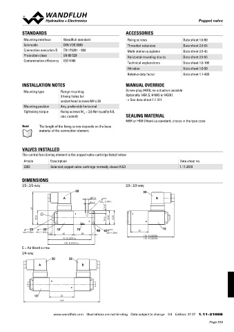
DIMENSIONS
3/2-; 2/2-way 3/2-; 2/2-way
30 35
A 7.5 B
4.3 MD= 2.6Nm
69 5.5
E
29 29 30
24.5
20 50 10 70 40 60 10
MD=9.5Nm MD=1.2Nm 4 42 38 7 MD=1.2Nm 38
100 B.22030b
93 B.22031a 100 B.32030b
100 B.32031a
E = Air bleed screw
3/4-way
30 35
A B
10 53
164
www.wandfluh.com Illustrations are not binding Data subject to change 3/4 Edition: 22 37 1.11-2100 E
Page 539