
Page 618 - Softbound_Edition_19_en
P. 618
Poppet valve
Poppet valve Poppet valve
ELECTRICAL CONNECTION Solenoid operated poppet valve detented
NG6
Namur Article no. 205.5011 Signal characteristics Flange construction ISO 4401-03
Device receptacle M12, 4 pole male Signal of the actuator Signal of the sensor ◆ 3/2-way
Mating connector M12, 4 pole female A / B Namur ◆ Q = 40 l/min x II 2 G Ex db IIC T6, T4
max
1 = Supply voltage + ◆ p = 350 bar x II 2 D Ex tb III C T80 °C, T130 °C
2 1 0 ≥ 4 mA max
2 = Signal x I M2 Ex db I Mb
3 4 1 ≤ 1 mA
Class I Division 1
1 Rv Attention: Class I Zone 1
I +
Do not apply a voltage >9V
2 -
Mating connector not incl. in delivery
DESCRIPTION APPLICATION
Direct operated 3/2-way solenoid poppet valve in flange construc- These valves are suitable for applications in explosion-hazard
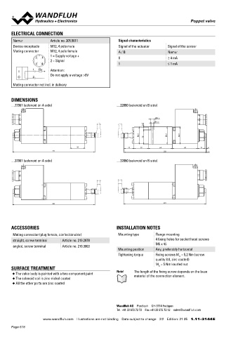
DIMENSIONS tion. By means of the pressure tight switching solenoid, the poppet areas, open cast and also in mines. Poppet valves are used where
…22061 (solenoid on A side) …22060 (solenoid on B side) valve spool is opened or closed acting against the spring and is held tight closing functions of the valve are essential like leakage-free
in the switching position by the form-closed detent. Due to the load holding, clamping or gripping.
poppet spool construction with pressure compensation on both
9.5 sides, the flow through the valve is possible in both directions. The
5.5 metallically sealing seat closes the valve virtually leak free. The
8
pressure tight encapsulated Ex-protection solenoid coil prevents
an explosion on the inside penetrating to the outside as well as an
45 46 45
38 ignitable surface temperature.
39 27 39 64 68 19 4 CERTIFICATES ACTUATION
221 221 1
Surface Mining Standard Z604 Actuation Switching solenoid, wet pin push type,
…32061 (solenoid on A side) …32060 (solenoid on B side) -25 °C to… -40 °C to… pressure tight
ATEX x x x x Execution MKY45 / 18x60 (data sheet 1.1-183)
IECEx x x x x MKU45 / 18x60 (data sheet 1.1-184)
Connection Cable gland for cable Ø 6,5…14 mm
CCC x x x x
EAC x x x x Attention! The UL execution is always supplied without cable
gland
Australia x x x x
MA x x
UL / CSA x x x
221 221
The certificates can be found on www.wandfluh.com STANDARDS
Explosion protection Directive 2014 / 34 / EU (ATEX)
Flameproof enclosure EN / IEC / UL 60079-1, 31
Cable entry EN 60079-0, 1, 7, 15, 31
ACCESSORIES INSTALLATION NOTES Mounting interface ISO 4401-03
Mating connector (plug female, confectionable) Mounting type Flange mounting Protection class EN 60 529
straight, screw terminal Article no. 219.2978 4 fixing holes for socket head screws Contamination ISO 4406
M5 x 45 efficiency
angled, screw terminal Article no. 219.3003
Mounting position Any, preferably horizontal SYMBOL
Tightening torque Fixing screws M = 5,2 Nm (screw Simplified Detailed
D
quality 8.8, zinc coated)
M = 5 Nm knurled nut A
D
SURFACE TREATMENT a a b b
◆ The valve body is painted with a two component paint Note! The length of the fixing screw depends on the base P T
material of the connection element.
◆ The solenoid coil is zinc-nickel coated
◆ All the other parts are zinc coated
A
a 0 b
a b
P T
Wandfluh AG Postfach CH-3714 Frutigen
Tel. +41 33 672 72 72 Fax +41 33 672 72 12 [email protected]
www.wandfluh.com Illustrations are not binding Data subject to change 2/2 Edition: 21 05 1.11-3144 E www.wandfluh.com Illustrations are not binding Data subject to change 1/4 Edition: 21 18 1.11-3146 E
Page 618