
Page 622 - Softbound_Edition_19_en
P. 622
Poppet valve
Poppet valve BH..04
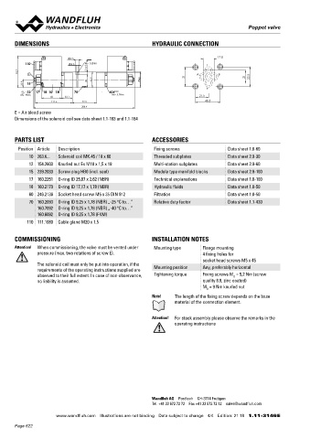
DIMENSIONS HYDRAULIC CONNECTION Poppet valve
Flange construction NG4-Mini
17.8 Wandfluh standard
9.5 ◆ hand operated
110 5.5 MD= 5.2Nm T 2/2-, 3/2- und 3/4-way
7.9 ◆
93.7 E 31 A B 21 32.5 ◆ normally open and normally closed
Q = 15 l/min
max
22.9 15 38 45.9 45 ◆ p = 350 bar
◆
P max
12 17 18 10 18 70 60
MD=9Nm MD= 5.2Nm 21.5
60 33.1
111.6 72.3 40.5
306.4 DESCRIPTION APPLICATION
E = Air bleed screw Direct operated 2/2-, 3/2 and 3/4-way poppet valve in flange Poppet valves are used where tight closing functions of the valve are
Dimensions of the solenoid coil see data sheet 1.1-183 and 1.1-184
construction. By means of the hand lever, the poppet valve spool is essential like leakage-free load holding, clamping or gripping. Minia-
opened or closed acting against the spring. Due to the poppet spool ture values are used where both, reduced dimensions and weight are
construction with pressure compensation on both sides, the flow important.
PARTS LIST ACCESSORIES through the valve is possible in both directions. The seat spool
Position Article Description Fixing screws Data sheet 1.0-60 guide is sealed by means of an O-ring. The metallically sealing seat
closes the valve virtually leak free.
10 263.6... Solenoid coil MK.45 / 18 x 60 Threaded subplates Data sheet 2.9-30
12 154.2603 Knurled nut Ex M18 x 1,5 x 18 Multi-station subplates Data sheet 2.9-60
15 239.2033 Screw plug HB0 (incl. seal) Module type manifold blocks Data sheet 2.9-100 SYMBOL
17 160.2251 O-ring ID 25,07 x 2,62 (NBR) Technical explanations Data sheet 1.0-100 BH22040b BH22041a BH32040b BH32041a
18 160.2170 O-ring ID 17,17 x 1,78 (NBR) Hydraulic fluids Data sheet 1.0-50 A A A A
60 246.2136 Socket head screw M5 x 35 DIN 912 Filtration Data sheet 1.0-50 a a b b a a b b a a b b a a b b
70 160.2093 O-ring ID 9,25 x 1,78 (NBR) „-25 °C to…” Relative duty factor Data sheet 1.1-430 P P P T P T
160.7092 O-ring ID 9,25 x 1,78 (NBR) „-40 °C to…” BH3404
160.6092 O-ring ID 9,25 x 1,78 (FKM)
A
110 111.1080 Cable gland M20 x 1,5
a a o ab b b
P T
COMMISSIONING INSTALLATION NOTES
Attention! When commissioning, the valve must be vented under Mounting type Flange mounting
pressure (max. two rotations of screw E). 4 fixing holes for
socket head screws M5 x 45 TYPE CODE
The solenoid coil must only be put into operation, if the 2/2 or 3/2 way execution B H 2 04 - #
requirements of the operating instructions supplied are Mounting position Any, preferably horizontal 3/4 way execution B H 3 4 04 - #
observed to their full extent. In case of non-observance, Tightening torque Fixing screws M = 5,2 Nm (screw
D
no liability is assumed. quality 8.8, zinc coated) Mounting interface according to Wandfluh standard
M = 9 Nm knurled nut
D
Hand lever
Note! The length of the fixing screw depends on the base
material of the connection element. 2 way (connections) 2
3 way (connections) 3
Attention! For stack assembly please observe the remarks in the 2 switching positions
operating instructions 4 switching positions
Nominal size 4-Mini
Normally closed Hand lever on A-side 1a
Normally open Hand lever on B-side 0b
Sealing material NBR
FKM (Viton) D1
Design index (subject to change)
1.11-5120
Wandfluh AG Postfach CH-3714 Frutigen
Tel. +41 33 672 72 72 Fax +41 33 672 72 12 [email protected]
www.wandfluh.com Illustrations are not binding Data subject to change 4/4 Edition: 21 18 1.11-3146 E www.wandfluh.com Illustrations are not binding Data subject to change 1/3 Edition: 17 23 1.11-5120 E
Page 622