
Page 624 - Softbound_Edition_19_en
P. 624
BH..04
Poppet valve BH..04
GENERAL SPECIFICATIONS ACTUATION VALVES INSTALLED
Designation 2/2-, 3/2- and 3/4-way poppet valve Actuation Hand lever The central functioning element is the poppet valve cartridge NG4, data sheet 1.11-2020.
Construction Direct operated Actuation angle a = 5 ° DIMENSIONS
Mounting Flange construction Actuation force F = 20 - 120 N (depending on flow 3/2-; 2/2-way 3/2-; 2/2-way
b
Nominal size NG4-Mini according to Wandfluh direction and pressure)
standard
Actuation Hand operated STANDARDS
Ambient temperature -25…+70 °C (NBR) Mounting interface Wandfluh standard
-20…+70 °C (FKM)
Weight 0,95 kg (2/2- and 3/2-way) Contamination ISO 4406
efficiency
1,45 kg (3/4-way)
MTTFd 150 years
152
9.5
HYDRAULIC SPECIFICATIONS ACCESSORIES 5.5 MD= 5.2Nm
Working pressure p = 350 bar Fixing screws Data sheet 1.0-60 5.5
max
Maximum volume flow Q = 15 l/min, see characteristic Threaded subplates Data sheet 2.9-10
max
Volume flow direction Any (see characteristic) Multi-station subplates Data sheet 2.9-50 32.5 35 38
Leakage oil Seat tight, max. 0,05 ml / min (approx. 1 Module type manifold blocks Data sheet 2.9-90
drop / min) at 30 cSt 10
50
Fluid Mineral oil, other fluid on request Technical explanations Data sheet 1.0-100 MD= 2.6Nm 10 20 70 40 60 MD= 2.6Nm
2
2
Viscosity range 12 mm /s…320 mm /s Filtration Data sheet 1.0-50 41 54
56 54 10
Temperature range -20…+70 °C 114 BH22041a 124 BH22040b
124 BH32040b
fluid 124 BH32041a
Contamination Class 20 / 18 / 14 SURFACE TREATMENT
efficiency ◆ The valve body is painted with a two component paint 3/4-way
Filtration Required filtration grade ß 10…16 ≥ 75, ◆ The hand lever housing, the screws and the cover are zinc
see data sheet 1.0-50 coated PARTS LIST
Position Article Description
PERFORMANCE SPECIFICATIONS 10 253.2000 Hand control head BHII
Oil viscosity u = 30 mm /s 20 074.2703 Flange square
2
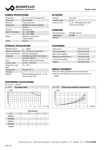
p = f (Q) Performance limits Δp = f (Q) Pressure drop volume flow characteristics 40 057.4201 Cover
p [bar] 2 1 p [bar] 50 249.1007 Socket head screw M4 x 63 DIN 912
350 K0172 40 K0154 60 246.1113 Socket head screw M4 x 12 DIN 912
300 35 70 160.2052 O-ring ID 5,28 x 1,78 (NBR)
250 30
200 25 160.6052 O-ring ID 5,28 x 1,78 (FKM)
20
150 15
100 10
50 5
0 0 SEALING MATERIAL
0 2 4 6 8 10 12 14 15 Q [l/min] 0 2 4 6 8 10 12 14 16 Q [l/min] 10 NBR or FKM (Viton) as standard, choice in the type code
82
Flow direction 202
Type P - A A - T A - P T - A INSTALLATION NOTES HYDRAULIC CONNECTION
BH22041a 1 - 1 -
Mounting type Flange mounting
BH22040b 1 - 2 -
3 fixing holes for 28
BH32041a 1 2 1 1 socket head screws M5 x 40 14
BH32040b 1 1 2 1 Mounting position Any, preferably horizontal
BH3404 1 1 1 1 Tightening torque Fixing screws M = 5,2 Nm (screw P
D
quality 8.8, zinc coated) A B 14 27
Note! The length of the fixing screw depends on the base T T0
material of the connection element.
Wandfluh AG Postfach CH-3714 Frutigen
Tel. +41 33 672 72 72 Fax +41 33 672 72 12 [email protected]
www.wandfluh.com Abbildung unverbindlich Änderungen vorbehalten 2/3 Ausgabe: 17 23 1.11-5120 D www.wandfluh.com Illustrations are not binding Data subject to change 3/3 Edition: 17 23 1.11-5120 E
Page 624