
Page 629 - Softbound_Edition_19_en
P. 629
AH..06
Poppet valve
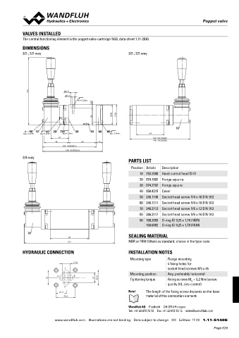
VALVES INSTALLED
The central functioning element is the poppet valve cartridge NG6, data sheet 1.11-2030.
DIMENSIONS
3/2-; 2/2-way 3/2-; 2/2-way
156 9.5
5.5
MD=5.2Nm
8
45 46
38
10
50 10 60 20 70 30 90 40 80
MD= 2.6Nm MD=2.6Nm MD=5.2Nm MD=5.2Nm 64
41 140 AH22060b
56 64 16 140 AH32060b
124 AH22061a
140 AH32061a
3/4-way
PARTS LIST
Position Article Description
10 253.2000 Hand control head BHII
20 074.1802 Flange squarre
30 074.2702 Flange square
40 058.4215 Cover
50 246.1140 Socket head screw M4 x 40 DIN 912
60 246.1111 Socket head screw M4 x 10 DIN 912
70 246.2112 Socket head screw M5 x 12 DIN 912
80 246.2117 Socket head screw M5 x 16 DIN 912
90 160.2093 O-ring ID 9,25 x 1,78 (NBR)
160.6092 O-ring ID 9,25 x 1,78 (FKM)
10
90 SEALING MATERIAL
211 NBR or FKM (Viton) as standard, choice in the type code
HYDRAULIC CONNECTION INSTALLATION NOTES
Mounting type Flange mounting
17.8 4 fixing holes for
T socket head screws M5 x 45
Mounting position Any, preferably horizontal
A B
31 21 32.5 Tightening torque Fixing screws M = 5,2 Nm (screw
D
quality 8.8, zinc coated)
P
21.5 Note! The length of the fixing screw depends on the base
40.5 material of the connection element.
Wandfluh AG Postfach CH-3714 Frutigen
Tel. +41 33 672 72 72 Fax +41 33 672 72 12 [email protected]
www.wandfluh.com Illustrations are not binding Data subject to change 3/3 Edition: 17 23 1.11-5140 E
Page 629