
Page 652 - Softbound_Edition_19_en
P. 652
Poppet valve
Poppet valve Poppet valve
GENERAL SPECIFICATIONS ACTUATION DIMENSIONS HYDRAULIC CONNECTION
Designation 3/2-way poppet valve Actuation Switching solenoid, wet pin push type,
Construction Direct operated pressure tight 30 17.8
Mounting Flange construction Execution Medium: SIN45V (Data sheet 1.1-120) A 9.5 MD= 5.2Nm T
5.5
Nominal size NG6 according to ISO 4401-03 Super: SIS45V (Data sheet 1.1-125) 8 A B
Actuation Switching solenoid Connection Connector socket EN 175301 – 803 85 31 21 32.5
Ambient temperature -25…+70 °C (NBR) 45 E 45 46 P
-20…+70 °C (FKM) 38 21.5
Weight 1,8 kg 40.5
MTTFd 150 years 20 50 10 70 40 60 MD=5.2Nm
MD= 9.5Nm MD= 5.2Nm
4 64 64 15
153
E = Air bleed screw
ELECTRICAL SPECIFICATIONS HYDRAULIC SPECIFICATIONS
PARTS LIST MANUAL OVERRIDE
Protection class IP65 Working pressure Medium: Screw plug (HB0), no actuation possible
Relative duty factor 100 % DF p = 160 bar Position Article Description Optionally: HB6, HN(K) or HR(K)
max
Switching frequency 15'000 / h Super: 10 260.6... Solenoid SIN45V → See data sheet 1.1-311
Solenoid SIS45V
260.7...
Service life time 10 (number of switching cycles, p = 300 bar
7
max
theoretically) Maximum volume flow Q = 15 l/min, see characteristic 20 239.2033 Screw plug HB0 (incl. seal) STANDARDS
max
Voltage tolerance ± 10 % with regard to nominal voltage Volume flow direction Any 30 219.2001 Electric plug A (grey)
Standard nominal 12 VDC, 24VDC, 115 VAC, 230 VAC Leakage oil Seat tight, max. 0,05 ml / min (approx. 1 35 219.2002 Electric plug B (black) Mounting interface ISO 4401-03
voltage AC = 50 to 60 Hz, rectifier integrated in drop / min) at 30 cSt 40 058.4215 Cover Solenoids DIN VDE 0580
the connector socket Fluid Mineral oil, other fluid on request 50 246.2160 Socket head screw M5 x 60 DIN 912 Connection execution D EN 175301 – 803
2
Viscosity range 12 mm /s…320 mm /s Protection class EN 60 529
2
Note! Other electrical specifications see data sheet 1.1-120 60 246.2117 Socket head screw M5 x 16 DIN 912 Contamination efficiency ISO 4406
(Medium) and 1.1-125 (Super) Temperature range -20…+70 °C 70 160.2093 O-ring ID 9,25 x 1,78 (NBR)
fluid
Contamination Class 20 / 18 / 14 160.6092 O-ring ID 9,25 x 1,78 (FKM)
efficiency
Filtration Required filtration grade ß 10…16 ≥ 75, SEALING MATERIAL ACCESSORIES
see data sheet 1.0-50 NBR or FKM (Viton) as standard, choice in the type code Fixing screws Data sheet 1.0-60
Threaded subplates Data sheet 2.9-05
Multi-station subplates Data sheet 2.9-45
SURFACE TREATMENT Horizontal mounting blocks Data sheet 2.9-85
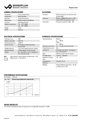
PERFORMANCE SPECIFICATIONS ◆ The valve body is painted with a two component paint Technical explanations Data sheet 1.0-100
Oil viscosity u = 30 mm /s ◆ The solenoid and the cover are zinc coated Hydraulic fluids Data sheet 1.0-50
2
◆ The socket head screws are zinc coated
∆p = f (Q) Pressure drop volume flow characteristic Filtration Data sheet 1.0-50
p [bar] Relative duty factor Data sheet 1.1-430
12 K1129
8 INSTALLATION NOTES COMMISSIONING
4 Mounting type Flange mounting Attention! When commissioning, the valve must be vented under
pressure (max. two rotations of screw E).
4 fixing holes for
0 socket head screws M5 x 45
0 5 10 15 20 Q [l/min] Mounting position Any, preferably horizontal
Tightening torque Fixing screws M = 5,2 Nm (screw
D
quality 8.8, zinc coated)
Note! The length of the fixing screw depends on the base
material of the connection element.
VALVES INSTALLED
The central functioning element is the poppet valve cartridge NG6, data sheet 1.11-2030.
Wandfluh AG Postfach CH-3714 Frutigen
Tel. +41 33 672 72 72 Fax +41 33 672 72 12 [email protected]
www.wandfluh.com Illustrations are not binding Data subject to change 2/3 Edition: 17 26 1.11-10010 E www.wandfluh.com Illustrations are not binding Data subject to change 3/3 Edition: 17 26 1.11-10010 E
Page 652