Page 648 - Softbound_Edition_19_en
P. 648

Poppet valve
                                                                                                Poppet valve                                                                                                                 Poppet valve


       GENERAL SPECIFICATIONS                              ACTUATION                                                               VALVES INSTALLED
       Designation        2/2-, 3/2- and 3/4-way poppet valve  Actuation       Pneumatically                                       The central functioning element is the poppet valve cartridge NG10, data sheet 1.11-2040.
       Construction       Direct operated                   Execution          Actuation AKI
       Mounting           Flange construction               Pilot pressure     p st min  = see characteristic                      DIMENSIONS
       Nominal size       NG10 according to ISO 4401-05                        p st max  = 8 bar                                   3/2-; 2/2-way                                        3/2-; 2/2-way
       Actuation          Pneumatically operated            Control volume     V = 10 cm 3                                                            10.5
       Ambient temperature  -25…+70 °C (NBR)                                                                                              G1/8"        6.5   MD= 8.9Nm   7
                          -20…+70 °C (FKM)
       Weight             4,1 kg (2/2- and 3/2-way)
                          5,4 kg (3/4-way)                                                                                           60                                    60   62
                                                                                                                                                                 55
       MTTFd              150 years

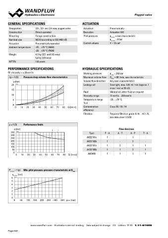
       PERFORMANCE SPECIFICATIONS                          HYDRAULIC SPECIFICATIONS                                                   50    10                70      40  60                                   10
                                                                                                                                    MD= 8.9Nm   57           93       18   MD= 8.9Nm                 93
                       2
       Oil viscosity u = 30 mm /s                           Working pressure   p  = 350 bar                                                                                                           178  AK22100b
                                                                                max                                                                  160  AK22101a                                    178  AK32100b
       Δp = f (Q)  Pressure drop volume-flow characteristics  Maximum volume flow  Q  = 80 l/min, see characteristic                                  178  AK32101a
                                                                                max
           p [bar]                                          Volume flow direction  Any (see characteristic)                             3/4-way
         20  K0157                                          Leakage oil        Seat tight, max. 0,05 ml / min (approx. 1                                                                HYDRAULIC CONNECTION
                                                                               drop / min) at 30 cSt
         15                                                                                                                                                                                                     54
                                                            Fluid              Mineral oil, other fluid on request
         10                                                 Viscosity range    12 mm /s…320 mm /s                                                                                                             P
                                                                                   2
                                                                                            2

          5                                                 Temperature range   -20…+70 °C                                                                                                                                   1.5
                                                                                                                                                                                                                               16.8
                                                            fluid                                                                        10                                                          46    A        B
          0                                                                                                                                                133                                                                 9.7
            0  10   20  30  40  50   60  70  80  Q [l/min]  Contamination      Class 20 / 18 / 14                                                          266                                           T            To
                                                            efficiency

                                                            Filtration         Required filtration grade ß 10…16 ≥ 75,                                                                                         20.8
                                                                               see data sheet 1.0-50                                                                                                         24

       p = f (Q)  Performance limits                                                                                               PARTS LIST                                           ACCESSORIES
           p [bar]                    2   1                                          Flow direction                                  Position Article  Description                       Fixing screws               Data sheet 1.0-60
         350  K0173                                             Type       P - A    A - T    A - P    T - A                              10 254.5000  Pneumatic actuation AKI            Threaded subplates          Data sheet 2.9-40
         300
         250                                                   AK22101a      1        -        1        -                                40 059.2200  Cover                              Multi-station subplates     Data sheet 2.9-70
         200                                                   AK22100b      1        -        2        -                                50 246.3166  Socket head screw M6 x 65 DIN 912  Module type manifold blocks  Data sheet 2.9-110
         150                                                   AK32101a      1        2        1        1                                60 246.3121  Socket head screw M6 x 20 DIN 912  Technical explanations      Data sheet 1.0-100
         100
          50                                                   AK32100b      1        1        2        1                                70 160.2140  O-ring ID 14,00 x 1,78 (NBR)       Filtration                  Data sheet 1.0-50
           0                                                   AK3410        1        1        1        1                                   160.6141  O-ring ID 14,00 x 1,78 (FKM)
            0   10  20  30   40  50  60  70   80  Q [l/min]

                                                                                                                                   SURFACE TREATMENT                                    SEALING MATERIAL
                                                                                                                                    ◆  The valve body is painted with a two component paint  NBR or FKM (Viton) as standard, choice in the type code
       P    = f (p)  Min. pilot pressure-pressure characteristic at Q                                                               ◆  The pneumatic actuation, the cover and the socket head screws
        st min                                      max                                                                               are zinc coated
          p           [bar]
           st min
         6  K0174
         5                                                                                                                         INSTALLATION NOTES                                   MANUAL OVERRIDE
         4                                                                                                                          Mounting type      Flange mounting                   In mechanical control head integrated. Actuation by pressing the pin
         3                                                                                                                                             4 fixing holes for
         2                                                                                                                                             socket head screws M5 x 65
         1                                                                                                                                                                              STANDARDS
         0                                                                                                                          Mounting position  Any, preferably horizontal
           0   50   100  150  200  250  300  350 pxxx [bar]                                                                         Tightening torque  Fixing screws M  = 8,9 Nm (quality 8.8,   Mounting interface  ISO 4401-05
                                                                                                                                                                   D
                                                                                                                                                       zinc-coated)                      Contamination      ISO 4406
                                                                                                                                                                                         efficiency
                                                                                                                                   Note!    The length of the fixing screw depends on the base
                                                                                                                                            material of the connection element.
                                                                                                                                                                                        Wandfluh AG  Postfach  CH-3714 Frutigen
                                                                                                                                                                                        Tel. +41 33 672 72 72  Fax +41 33 672 72 12  [email protected]

                       www.wandfluh.com  Illustrations are not binding  Data subject to change  2/3  Edition: 17 20  1.11-6160 E                   www.wandfluh.com  Illustrations are not binding  Data subject to change  3/3  Edition: 17 20  1.11-6160 E
       Page 648
   643   644   645   646   647   648   649   650   651   652   653