
Page 644 - Softbound_Edition_19_en
P. 644
Poppet valve
Poppet valve Poppet valve
GENERAL SPECIFICATIONS ACTUATION VALVES INSTALLED
Designation 2/2-, 3/2- and 3/4-way poppet valve Actuation Pneumatically The central functioning element is the poppet valve cartridge listed below
Construction Direct operated Execution Actuation CKII #2 Article Description Data sheet no.
Mounting Flange construction Pilot pressure p V min = 2 bar bei p = 20 bar 2206 Solenoid poppet valve cartridge normally closed NG6 1.11-2030
T
Nominal size NG6 according to ISO 4401-03 p V min = 5,5 bar bei p = 200 bar
T
Actuation Pneumatically operated Control volume V = 6,9 cm 3
Ambient temperature -25…+70 °C
Weight 1,7 kg (2/2- and 3/2-way) DIMENSIONS
2,5 kg (3/4-way) 3/2-; 2/2-way 3/2-; 2/2-way
MTTFd 150 years 9.5
G1/8" 5.5
MD= 5.2Nm
8
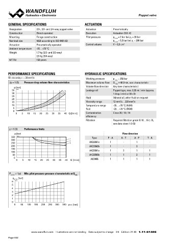
PERFORMANCE SPECIFICATIONS HYDRAULIC SPECIFICATIONS
Oil viscosity u = 30 mm /s Working pressure p = 350 bar 45 38 45 46 10
2
max
Δp = f (Q) Pressure drop volume-flow characteristics Maximum volume flow Q = 40 l/min, see characteristic 64
max
p [bar] Volume flow direction Any (see characteristic) 10 138 AK22060b
138 AK32060b
50
35 K0078 Leakage oil Poppet type, max. 0,05 ml / min (approx. MD= 5.2Nm 70 40 60 MD=5.2Nm
30 1 drop / min) at 30 cSt 54 64 15
25 Fluid Mineral oil, other fluid on request 123 AK22061a
20 138 AK32061a
2
2
15 Viscosity range 12 mm /s…320 mm /s
10 Temperature range -25…+70 °C (NBR)
5 fluid -20…+70 °C (FKM) HYDRAULIC CONNECTION
0
0 5 10 15 20 25 30 35 40 Q [l/min] Contamination Class 20 / 18 / 14
efficiency 3/4-way 17.8
Filtration Required filtration grade ß 10…16 ≥ 75, T
see data sheet 1.0-50
A B
p = f (Q) Performance limits 31 21 32.5
p [bar] Flow direction P
350 K0177 Type P - A A - T A - P T - A 21.5
300 1 2 10 90 40.5
250 3 AK22061a 1 - 1 - 208 AK3406
200 AK22060b 1 - 3 -
150 AK32061a 1 2 1 1
100
50 AK32060b 1 1 2 1
0 AK3406 1 1 1 1
0 5 10 15 20 25 30 35 40 Q [l/min] PARTS LIST ACCESSORIES
Position Article Description Fixing screws Data sheet 1.0-60
10 254.4061 Pneumatic actuation CK II #2 Threaded subplates Data sheet 2.9-30
P = f (p) Min. pilot pressure-pressure characteristic at Q
st min max 40 058.4215 Cover Multi-station subplates Data sheet 2.9-60
p [bar] 50 246.2160 Socket head screw M5 x 60 DIN 912 Horizontal mounting blocks Data sheet 2.9-100
st min
6 K0174 60 246.2117 Socket head screw M5 x 16 DIN 912 Technical explanations Data sheet 1.0-100
5 70 160.2093 O-ring ID 9,25 x 1,78 (NBR) Filtration Data sheet 1.0-50
4
3 160.6092 O-ring ID 9,25 x 1,78 (FKM)
2
1
0
0 50 100 150 200 250 300 350 pxxx [bar]
www.wandfluh.com Illustrations are not binding Data subject to change 2/4 Edition: 21 48 1.11-6140 E www.wandfluh.com Illustrations are not binding Data subject to change 3/4 Edition: 21 48 1.11-6140 E
Page 644