
Page 640 - Softbound_Edition_19_en
P. 640
Poppet valve
Poppet valve Poppet valve
GENERAL SPECIFICATIONS ACTUATION VALVES INSTALLED
Designation 2/2-, 3/2- and 3/4-way poppet valve Actuation Pneumatically The central functioning element is the poppet valve cartridge NG4, data sheet 1.11-2020.
Construction Direct operated Execution Actuation BKII DIMENSIONS
Mounting Flange construction Pilot pressure p st min = see characteristic 3/2-; 2/2-way 3/2-; 2/2-way
Nominal size NG4-Mini according to Wandfluh p st max = 8 bar 9.5
standard Control volume V = 2,5 cm 3
Actuation Pneumatically operated G1/8" 5.5 MD=5.2Nm
Ambient temperature -25…+70 °C (NBR) 5.5
-20…+70 °C (FKM)
Weight 0,9 kg (2/2- et 3/2-way) 35 35 38
1,2 kg (3/4-way) 32.5
MTTFd 150 years
50 10 70 40 60 10
PERFORMANCE SPECIFICATIONS HYDRAULIC SPECIFICATIONS MD=2.6Nm 38 54 10 MD=2.6Nm 54
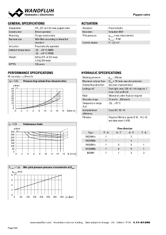
Oil viscosity u = 30 mm /s Working pressure p = 350 bar 99 BK22041a 109 BK22040b
2
max
Δp = f (Q) Pressure drop volume flow characteristics Maximum volume flow Q = 15 l/min, see characteristic 109 BK32041a 109 BK32040b
max
p [bar] Volume flow direction Any (see characteristic) 3/4-way
40 K0154 Leakage oil Seat tight, max. 0,05 ml / min (approx. 1 HYDRAULIC CONNECTION
35 drop / min) at 30 cSt
30
25 Fluid Mineral oil, other fluid on request 28
20 Viscosity range 12 mm /s…320 mm /s
2
2
15 14
10 Temperature range -20…+70 °C
5 fluid P
0 10
0 2 4 6 8 10 12 14 16 Q [l/min] Contamination Class 20 / 18 / 14 82 A B 14 27
efficiency
173
Filtration Required filtration grade ß 10…16 ≥ 75, T T0
see data sheet 1.0-50
p = f (Q) Performance limits
p [bar] 1 Flow direction PARTS LIST ACCESSORIES
350 K0153 2 Type P - A A - T A - P T - A Position Article Description Fixing screws Data sheet 1.0-60
300 3 4 10 254.2000 Pneumatic actuation BK II Threaded subplates Data sheet 2.9-10
250 5 BK22041a 1 - 2 -
200 BK22040b 1 - 4 - 40 057.4201 Cover Multi-station subplates Data sheet 2.9-50
150 BK32041a 1 3 5 1 50 246.1146 Socket head screw M4 x 45 DIN 912 Module type manifold blocks Data sheet 2.9-90
100
50 BK32040b 1 4 5 1 60 246.1113 Socket head screw M4 x 12 DIN 912 Technical explanations Data sheet 1.0-100
0 BK3404 1 1 2 2 70 160.2052 O-ring ID 5,28 x 1,78 (NBR) Filtration Data sheet 1.0-50
0 2 4 6 8 10 12 14 16 Q [l/min]
160.6052 O-ring ID 5,28 x 1,78 (FKM)
SURFACE TREATMENT SEALING MATERIAL
P = f (p) Min. pilot pressure-pressure characteristic at Q ◆ The valve body is painted with a two component paint NBR or FKM (Viton) as standard, choice in the type code
st min max
◆ The pneumatic actuation, the cover and the socket head screws
p [bar] are zinc coated
st min
8 K0241
INSTALLATION NOTES MANUAL OVERRIDE
6 In mechanical control head integrated. Actuation by pressing the pin
Mounting type Flange mounting
4 3 fixing holes for
socket head screws M5 x 40
2
Mounting position Any, preferably horizontal STANDARDS
0 Tightening torque Fixing screws M = 5,2 Nm (screw
0 50 100 150 200 250 300 350 pxxx[bar] D Mounting interface Wandfluh standard
quality 8.8, zinc coated) Contamination ISO 4406
Note! The length of the fixing screw depends on the base efficiency
material of the connection element.
Wandfluh AG Postfach CH-3714 Frutigen
Tel. +41 33 672 72 72 Fax +41 33 672 72 12 [email protected]
www.wandfluh.com Illustrations are not binding Data subject to change 2/3 Edition: 17 20 1.11-6120 E www.wandfluh.com Illustrations are not binding Data subject to change 3/3 Edition: 17 20 1.11-6120 E
Page 640