
Page 689 - Softbound_Edition_19_en
P. 689
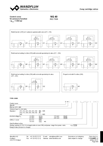
2-way cartridge valves
 2-2-way slip-in cartridge                                                                 2-2-way slip-in cartridge

 GENERAL SPECIFICATIONS  HYDRAULIC SPECIFICATIONS
 Construction  Control cover for directional function  Fluid             Mineral oil, other fluid on request  Control cover  NG 40
 Mounting position   any  Contamination efficiency  ISO 4406:1999, class 18/16/13  for pressure function  ISO 7368
 Installation dimension   see dimension              (Required filtration grade ß6...10≥75)  • p    = 350 bar
          to ISO 7368  see data sheet no. 1.0-50/2  max
 see data sheet 2.13-1023  Viskosity range       12 mm /s to 320 mm /s
 2
 2
 Ambient temperature   -25…+70 °C  Fluid temperature  -20…+70 °C
 Fastening torque   M  = 190 Nm (Qual. 8.8) for fixing screws  Operation pressure  p    = 350 bar
 D  max
              Relief function (210) with solenoid operated pilot valve (211...214)
 DIMENSIONS

    211, 221, 231   212, 222, 232   210, 220, 230, 240
 1  2  3  4  5
  90.2    117.2
 1  2  3  4  5                210                 211                  212                 213                 214
 B
 211   90.2    13.5   117.2   212  X  X               X                   X                   X
 A
  13.5                        210                 211                  212                 213                 214
 211  B  A  212  X  x  X    Y     X  x    X     Y     X  x    X     Y     X  x    X     Y     X  x    X     Y
 A      A
                 x   X      Y  210   x    X     Y  211   x    X     Y  212   x    X     Y  213   x    X     Y  214
              X                   X                   X                   X                   X
 A      A     Relief and unloading function (220) with solenoid operated pilot valve (221...224)
  99    50   X=G1/4"
                 x   X      Y        x    X     Y        x    X     Y        x    X     Y        x    X     Y
  50   X=G1/4"   99    50   X=G1/4"
  50   X=G1/4"  X             220  X              221  X               222  X              223  X              224
  4.7                         220                 221                  222                 223                 224
              X  x   X      Y     X  x    X     Y     X  x    X     Y     X  x    X     Y     X  x    X     Y
 20  30  40  60  10  50   4.7
                 x   X      Y  220   x    X     Y  221   x    X     Y  222   x    X     Y  223   x    X     Y  224
 B   92.45    119.45   B  X       X                   X                   X                   X
 10
    20 214, 224, 234   60 213, 223, 233
 50
 30
 40
 B   92.45    119.45   B  x  X  Y    x    X     Y        x    X     Y        x    X     Y        x    X     Y
  13.5        Relief and unloading function (230) with solenoid operated pilot valve   Proportional relief function (240)
 214  B  A  213
              (231...234)
  13.5                        230                 232                                      240
 214  B  A  213  X                X                                       X
  100   X=G1/4"  X  x  X    Y  230  X  x  X     Y  232                    X  x    X     Y  240
  96    100   X=G1/4"  X  x  X  Y  230  X  x  X  Y  232                   X  x    X     Y  240
  50   X=G1/4"   96   x  X  Y        x    X     Y                            x    X     Y
 C
  50   X=G1/4"   108
 C

  108    108
            TYPE CODE
  108                                                                       D  40      -           /   -       #

 VALVES  P  PARTS LIST  Control cover
            Size 40
  100

     IND


 X=G1/4"
 A
 Pilot operated  211, 221, 231  WDMFA06-AB2  Data sheet 1.2-59  Position       Article       Description  Gezeichnet  03.12.2020  GOB  Pilot no. 210...240
 Geprüft


 07.12.2020

 P
     TK
 D  valves:   212, 222, 232  WDMFA06-AB1  Data sheet 1.2-59                     Freigegeben  08.12.2020  IND  Solenoid type for pilot valve
 T
 Name Änderungsnr.
 03.12.2020
 Änderungsbeschrieb
 Serie freigegeben
 A
     100   X=G1/4"  213, 223, 233  AS22061a   Data sheet 1.11-2140  10  Rev.  Datum      063.2036     Plate to 210, 220, 230, 240  Gezeichnet  M 1:2  07.12.2020  Gewicht Modellreferenz: Doknr. 0280852 / Konfiguration 002  Standard   211, 212, 221, 222, 231, 232   M .. / WD

     GOB


 Geprüft
 Ersetzt durch:
 2/2-Wege-Einbauventil Deckel NG32


     TK
 D     214, 224, 234  AS22060b   Data sheet 1.11-2140  Rev.  Datum    063.2037     Plate to other types  Freigegeben M 1:2  08.12.2020  6.271 kg  213, 214, 223, 224, 233, 234   S
 Ersatz für:
 T
 Serie freigegeben
 Änderungsbeschrieb
 Name Änderungsnr.
    Format
 Locking screw VSTI G1/4"
 20  D32 Druckfunktion  Dok.-Nr.  0280851 Gewicht Modellreferenz: Doknr. 0280852 / Konfiguration 002  240   .. / WD
 238.2406
    A3
 Ersetzt durch:
 Pressure   210...214   BA.PM22   Data sheet 2.1-540  2/2-Wege-Einbauventil Deckel NG32  Ersatz für:   6.271 kg
 Cyl. screw M16x55 DIN912
  108
 246.7156
 valves:   220...224   BY.PM22   Data sheet 2.1-544  30  D32 Druckfunktion  Dokument darf ohne schriftliche Einwilligung weder kopiert,  Art.-Nr. DB 1.12-435  Revision  Nominal voltage U N      12 VDC    G12  115 VAC   R115
 Dok.-Nr.
    Format
    00
                                   24 VDC
                                                                           R230
 0280851
 verwertet noch an Dritte weitergegeben werden.
                                                               230 VAC
                                              G24
    A3
   1  230...234   BX.PM22   Data sheet 2.1-544  40  221.2470  Pin ∅5x16 DIN1481 C:\00_Wandfluh\Verkauf\Dokumentation\Reg1.12\DB 1.12-435\0280851  Blatt 1 von 1
 Zuwiderhandlung ist strafbar und wird gerichtlich verfolgt.
 2
    240    108   BDPPM22   Data sheet 2.3-540  Dokument darf ohne schriftliche Einwilligung weder kopiert,  Art.-Nr.  DB 1.12-435  Revision  Orifice in cover       0.6 mm    0.6
 verwertet noch an Dritte weitergegeben werden.
 50  160.2092  O-ring ID 9,19x2,62  00  1.0 mm    1.0   etc.
 Zuwiderhandlung ist strafbar und wird gerichtlich verfolgt.
 2
 1
 Pressure   210...214   63, 160, 315, 350 [bar]  60  118.2032  Orifice M5 / 0,8 x 5  C:\00_Wandfluh\Verkauf\Dokumentation\Reg1.12\DB 1.12-435\0280851  Blatt 1 von 1  Omit if without orifice
 ranges from   220...224   100, 315 [bar]             118.2052  Orifice M5 / 0,9 x 5  Setting versions S, D, K, A (not applicable at cover 240) and press. range from press. valve        e.g.  D250
 press. valves:  230...234   100, 315 [bar]  118.2031  Orifice M5 / 1,0 x 5  Design-Index (Subject to change)
    240   40, 100, 200, 315 [bar]  118.2058  Orifice M5 / 1,2 x 5
 118.2072  Orifice M5 / 1,5 x 5
 Wandfluh AG   Tel.  +41 33 672 72 72   E-mail:  [email protected]   Illustrations not obligatory   Data sheet no.   Wandfluh AG   Tel.  +41 33 672 72 72   E-mail:  [email protected]   Illustrations not obligatory   Data sheet no.
 Postfach   Fax  +41 33 672 72 12   Internet:  www.wandfluh.com   Data subject to change   1.12-435E 2/2   Postfach   Fax  +41 33 672 72 12   Internet:  www.wandfluh.com   Data subject to change   1.12-440E 1/2
 CH-3714 Frutigen                   Edition 20 51  CH-3714 Frutigen                                      Edition 20 51
                                                                                                            Page 689