
Page 694 - Softbound_Edition_19_en
P. 694
2-way cartridge valves
2-2-way slip-in cartridge 2-2-way slip-in cartridge
GENERAL SPECIFICATIONS HYDRAULIC SPECIFICATIONS Control cover NG 32
Construction Control cover for check function Fluid Mineral oil, other fluid on request for check function
Mounting position any Contamination efficiency ISO 4406:1999, class 18/16/13 ISO 7368
Installation dimension see dimension to ISO 7368 see (Required filtration grade ß6...10≥75) • p max = 350 bar
data sheet 2.13-1022 see data sheet no. 1.0-50/2
Ambient temperature -25…+70 °C Viskosity range 12 mm /s bis 320 mm /s
2
2
Fastening torque M = 80 Nm (Qual. 8.8) for fixing screws Fluid temperature -20…+70 °C
D
Operation pressure p = 350 bar
max
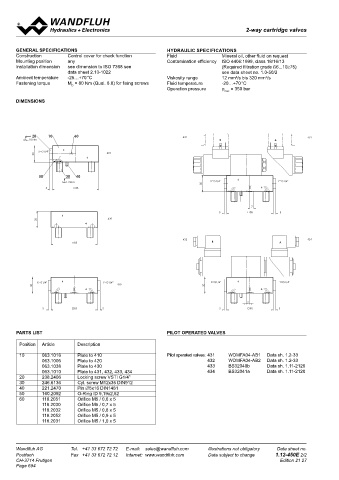
DIMENSIONS
Non-return function Non-return function in combination with Non-return function for control via X or Y
CS..-10/...-C7 with integrated shuttle valve
1 2 3 4 5 6 7 8
20 10 60 432 431
MD= 18 Nm B A
A A
X=G1/4" 410
30
50 30 40
MD=75Nm X=G1/4" Y=G1/4"
30
5 85
B B With integrated shuttle valve (430) and additional pilot valve (431... 434)
7
5 85 5
30 420
C C
433 434
85 B A
D D
X=G1/4" Y=G1/4" X=G1/4" Y=G1/4"
30 430 30
7
5 85 5 5 85 5
TYPE CODE
Gezeichnet 04.02.2016 BEH
E 01 16.02.2016 BEH Alle Varianten auf Datenblatt dargestellt Geprüft 11.11.2016 KL E D 32 - / #
02 07.11.2016 BEH O-Ringe eingeblendet, Symbol dazu Freigegeben 14.11.2016 TK
Rev. Datum Name Änderungsnr. Änderungsbeschrieb M 1:1 Serie freigegeben Control cover
Gewicht
CS-Deckel NG25
PARTS LIST PILOT OPERATED VALVES Ersetzt durch: 2.542 kg
Ersatz für:
Format
Dok.-Nr.
D25.../W 0192522 A2 Nominal size 32
Dokument darf ohne schriftliche Einwilligung weder kopiert, Art.-Nr. Revision
verwertet noch an Dritte weitergegeben werden. DB 1.12-450 02 Pilot no. 410...434
Position Article 2 Description 3 4 5 Zuwiderhandlung ist strafbar und wird gerichtlich verfolgt. Blatt 1 von 1
1
C:\00_Wandfluh\Verkauf\Dokumentation\Reg1.12\0192522
Solenoid type for pilot valve
10 063.1016 Plate to 410 Pilot operated valves: 431 WDMFA04-AB1 Data sh. 1.2-33 Standard 431, 432 M .. / WD
063.1006 Plate to 420 432 WDMFA04-AB2 Data sh. 1.2-33 433, 434 S
063.1038 Plate to 430 433 BS32040b Data sh. 1.11-2120 Nominal voltage U 12 VDC G12 115 VAC R115
063.1010 Plate to 431, 432, 433, 434 434 BS32041a Data sh. 1.11-2120 N 24 VDC G24 230 VAC R230
20 238.2406 Locking screw VSTI G1/4"
30 246.6136 Cyl. screw M12x35 DIN912 Orifice in cover 0.8 mm 0.8
40 221.2470 Pin ∅5x16 DIN1481 1.0 mm 1.0 etc.
50 160.2092 O-Ring ID 9,19x2,62 Omit if without orifice
60 118.2051 Orifice M5 / 0,6 x 5 Design-Index (Subject to change)
118.2030 Orifice M5 / 0,7 x 5
118.2032 Orifice M5 / 0,8 x 5
118.2052 Orifice M5 / 0,9 x 5
118.2031 Orifice M5 / 1,0 x 5
Wandfluh AG Tel. +41 33 672 72 72 E-mail: [email protected] Illustrations not obligatory Data sheet no. Wandfluh AG Tel. +41 33 672 72 72 E-mail: [email protected] Illustrations not obligatory Data sheet no.
Postfach Fax +41 33 672 72 12 Internet: www.wandfluh.com Data subject to change 1.12-450E 2/2 Postfach Fax +41 33 672 72 12 Internet: www.wandfluh.com Data subject to change 1.12-455E 1/2
CH-3714 Frutigen Edition 21 27 CH-3714 Frutigen Edition 20 32
Page 694