
Page 699 - Softbound_Edition_19_en
P. 699
2-2-way slip-in cartridge 2 position, 2 way cartridge valves
2-way cartridge valves
GENERAL SPECIFICATIONS HYDRAULIC SPECIFICATIONS Cartridge valve body NG16
Construction Control cover for check function Fluid Mineral oil, other fluid on request • p = 350 bar
Mounting position any Contamination efficiency ISO 4406:1999, class 18/16/13 max NG25 ISO 7368
Installation dimension see dimension to ISO 7368 see (Required filtration grade ß6...10≥75)
data sheet 2.13-1024 see data sheet no. 1.0-50/2 NG32
Ambient temperature -25…+70 °C Viskosity range 12 mm /s to 320 mm /s
2
2
Fastening torque M = 370 Nm (qual. 8.8) for fixing screws Fluid temperature -20…+70 °C
D
Operation pressure p = 350 bar
max
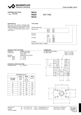
DESCRIPTION TYPE CODE
DIMENSIONS
Valve body with cavity for cartridge (logic K #
element) size NG16, NG25 and NG32 to ISO
7368 / DIN 24342 (see data sheets 1.12-210, Cartridge valve body
1.12-220, 1.12-230). Body surface is zinc-
1 2 3 4 5 6 7 8 Nominal size NG16 16
nickel coated. NG25 25
432 431 NG32 32
A B
20 10 60 Port size
MD=18 Nm
for NG16 G1/2" 12
A A
G3/4" 34
X=G1/4" for NG25 G1" 100
35 410 G1 1/4" 114
G1 1/2" 112
for NG32 G1 1/2" 112
X=G1/4" Y=G1/4" Design-Index (Subject to change)
35
B 50 30 40 B
MD= 390 Nm
5 125
GENERAL SPECIFICATIONS DIMENSIONS
9
5 125 5 Description Cartridge valve body For detailed cavity drawing
Nominal size NG16, NG25, NG32 see data sheets: NG16 = 2.13-1021
35 420 433 434 to ISO 7368 NG25 = 2.13-1022
A B NG32 = 2.13-1023
C C Mounting 4 tapped holes for fixation
Weight: NG16 m = 2,6 kg
NG25 m = 8,7 kg
NG32 m = 11,4 kg
125
HYDRAULIC SPECIFICATIONS
Working pressure p = 350 bar
X=G1/4" Y=G1/4" max
D D
35
9
5 125 5
Dimensions (in mm)
01 12.02.2016 BEH Alle Variante auf Datenblatt dargestellt Gezeichnet 04.02.2016 BEH NG16 NG25 NG32
E 02 07.11.2016 BEH WDMFA06 gedreht - Korrektur Geprüft 24.11.2016 KL E
03 23.11.2016 BEH Beschriftung korrigiert Freigegeben 24.11.2016 TK
Rev. Datum Name Änderungsnr. Änderungsbeschrieb M 1:1 Serie freigegeben Port sizes G1/2" G1" G1 1/2"
Gewicht
CS-Deckel NG40 Ersetzt durch: 5.764 kg
Ersatz für:
PARTS LIST PILOT OPERATED VALVES Dok.-Nr. 0192528 Format A and B G3/4" G1 1/4"
D40.../W.
A2
Dokument darf ohne schriftliche Einwilligung weder kopiert, Art.-Nr. Revision G1 1/2"
verwertet noch an Dritte weitergegeben werden. DB 1.12-460 03
Zuwiderhandlung ist strafbar und wird gerichtlich verfolgt.
Position Article 2 Description 3 4 5 C:\00_Wand uh\Verkauf\Dokumentation\Reg1.12\0192528 Blatt 1 von 1 C 30 44 52
1
10 063.3001 Plate to 410 Pilot operated valves: 431 WDMFA06-AB1 Data sh. 1.2-59 D 90 125 130
063.3005 Plate to 420 432 WDMFA06-AB2 Data sh. 1.2-59 E 70 90 105
063.3010 Plate to 430 433 AS32060b Data sh. 1.11-2140
063.3017 Plate to 431, 432, 433, 434 434 AS32061a Data sh. 1.11-2140 F 70 125 145
20 238.2406 Locking screw VSTI G1/4" G 54 105 121
238.3402 Locking screw VSTI G3/8" H 54 70 81
30 246.8140 Cyl. screw M20x40 DIN912
40 221.2470 Pin ∅5x16 DIN1481 I M6 M8 M10
50 160.2107 O-Ring ID 10,77x2,62
60 118.2032 Orifice M5 / 0,8 x 5
118.2052 Orifice M5 / 0,9 x 5
118.2031 Orifice M5 / 1,0 x 5
118.2058 Orifice M5 / 1,2 x 5
118.2072 Orifice M5 / 1,5 x 5
Wandfluh AG Tel. +41 33 672 72 72 E-mail: [email protected] Illustrations not obligatory Data sheet no. Wandfluh AG Tel. +41 33 672 72 72 E-mail: [email protected] Illustrations not obligatory Data sheet no.
Postfach Fax +41 33 672 72 12 Internet: www.wandfluh.com Data subject to change 1.12-460E 2/2 Postfach Fax +41 33 672 72 12 Internet: www.wandfluh.com Data subject to change 1.12-505E 1/1
CH-3714 Frutigen Edition 20 32 CH-3714 Frutigen Edition 21 47
Page 699