
Page 711 - Softbound_Edition_19_en
P. 711
1
2
(1 : 1)
18.5
2x M3
A
18.5 3 4 51 28.7 5 19.25 A
Digital amplifier electronics
Digital amplifier electronics PD2 51 Digital amplifier electronics PD2
19.25
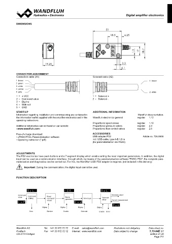
DIMENSIONS
Amplifier with analog interface B 28.7 51 B
ELECTRICAL SPECIFICATIONS 18.5 6.25
Protection class IP 67 acc. to EN 60 529 Dither Frequency adjustable 4…500 Hz
Supply voltage 8…32 V Factory setting 80 Hz
Residual ripple < +/-5 % Level adjustable 0…400 mA
Fuse Low Factory setting 180 mA 19.25
No-load current Approx. 20 mA Temperature drift <1 % at ∆T = 40 °C
Max. current Digital inputs 1 input high-active, no pull-up/down 1.5 17 28.7
consumption No-load current + 2,5 A per solenoid Switching threshold high 6...32 VDC 1 brown
Analog input 1 input non-differential Switching threshold low 0…1 VDC 2 green
Voltage / current (switchable by means of parameter) Usable as frequency input 3 white
0...+/- 10V or 0/4...20mA (frequency 5...5000 Hz) and as PWM input 19.25 4 yellow 3.3
Resolution 10-bit C (automatic frequency recognition) 5 grey C
Input resistance Voltage input >100 kΩ Ramps Adjustable 0…500 s 6.1
(Input current < 5 mA) USB interface Via digital input
Load for current input = 124 Ω Requires the Wandfluh USB adapter CONNECTOR ASSIGNMENT
Stabilised output 5 VDC EMV Connection cable (X1) Solenoid cable (X2)
voltage Max. load 20 mA Immunity EN 61 000-6-2 1 brown 1 brown
Solenoid current: Emission EN 61 000-6-4 2 green
• Minimal current I Adjustable 0…I max mA 3 white
min
Factory setting 150 mA 4 yellow
Adjustable I …2450 m A
• Maximal current I max min 5 grey 2 white
Factory setting 700 mA
1 = + VCC 1 = Solenoid +
2 = Command value 02 02.11.2015 BEH Ansicht für Befestigungsbohrungen hinzugefügt Gezeichnet 22.08.2014 ZUA
2 = Solenoid -
3 = Dig Inp 03 28.03.2017 BEH Massstab 1:1 - Format A3 Geprüft 21.07.2020 SMI
BLOCK DIAGRAM D 4 = Stab out 04 01.07.2020 SMI Bemassung Langlöcher geändert Freigegeben 21.07.2020 TK D
1 brown
5 = GND Rev. Datum Name Änderungsnr. Änderungsbeschrieb M 1:1 Serie freigegeben
Gewicht
brown X1-1 X2-1 Steckerverstärker Ersetzt durch: 0.018 kg
Ersatz für:
+VCC START-UP ADDITIONAL INFORMATION Dok.-Nr. Format
Information regarding installation and commissioning are contained in Wandfluh documentation-
PD2301D80-AA
0158797
A3
the information leaflet supplied with the amplifier electronics and in the Wandfluh electronics general register 1.13
2 white
operating instructions. Dokument darf ohne schriftliche Einwilligung weder kopiert, Art.-Nr. DB 1.13-64 Revision
verwertet noch an Dritte weitergegeben werden.
Zuwiderhandlung ist strafbar und wird gerichtlich verfolgt. register 1.10 04
Proportional spool valves
1 2 C:\00_Wandfluh\Artikelhierarchie\01_Verkaufsartikel\26_Elektronik\11_Verstärker\0158797 Blatt 1 von 1
Additional information can be found on our website: Proportional pressure valves register 2.3
«www.wandfluh.com» Proportional flow control valves register 2.6
grey X1-5
GND
Free-of-charge download: ACCESSORIES
• «PASO-PD2» Parameterisation software USB-adapter PD2 Article no. 726.9900
Internal Solenoid • Operating instruction (*.pdf) incl. USB-cable, type A-B 1,8 m
supply Supply PWM (for parameterisation via PASO)
Stabilised yellow X1-4
output
ADJUSTMENTS
A/D
The PD2 electronics have push-buttons and a 7 segment display which enable setting the most important parameters. In addition, the digital
input can be used as a communication interface, through which, by means of the parameterisation software "PASO-PD2", the complete para-
green X1-2
Analog input X2-2 meterisation and diagnostics can be carried out. For this, the Wandfluh USB-PD2 adapter is required. (not included in the delivery)
Voltage or current A/D
Important: During the communication, the digital input cannot be used.
FUNCTION DESCRIPTION
white X1-3
Digital input
Adapter Push-buttons 7 segment Command Command Fixed Ramp Solenoid Solenoid output
value
USB-PD2 FLASH display scaling command generator Valve type driver Current measurement
values
RAM
PASO / USB DigInp DigInp DigInp DigInp
Error Number Enable Solenoid Enable Error
Wandfluh AG Tel. +41 33 672 72 72 E-mail: [email protected] Illustrations not obligatory Data sheet no. Wandfluh AG Tel. +41 33 672 72 72 E-mail: [email protected] Illustrations not obligatory Data sheet no.
Postfach Fax +41 33 672 72 12 Internet: www.wandfluh.com Data subject to change 1.13-64E 2/7 Postfach Fax +41 33 672 72 12 Internet: www.wandfluh.com Data subject to change 1.13-64E 3/7
CH-3714 Frutigen Edition 21 20 CH-3714 Frutigen Edition 21 20
Page 711