
Page 707 - Softbound_Edition_19_en
P. 707
brown 2
brown 2
brown 2
brown 2
+ +
+ ++
Supply voltage
Supply voltage
Supply voltage
Supply voltage
Supply voltage
Stabilized output voltage
Stabilized output voltage
Stabilized output voltage
Stabilized output voltage
- - - - -
UU
U
grey 5
grey 5
grey 5
grey 5
grey 5
I I I I I
yellow 4
yellow 4
yellow 4
yellow 4
yellow 4
Solenoid
Solenoid
Solenoid
Stabilized output voltage
Solenoid
Stabilized output voltage
Solenoid
Stabilized output voltage
Stabilized output voltage
Stabilized output voltage
I-min
I-max
I-max
Ramp
Ramp
I-min
I-max
I-min
I-max
I-max
Ramp
Ramp
I-min
I-min
green 3
green 3
green 3
green 3
green 3
UU
U U
U
Preset value input
Preset value input
Preset value input
Preset value input
Preset value input
f f f f f
Dither
Dither
Dither
Dither
white 1
white 1
white 1
white 1
white 1
Release / block
Release / block
Release / block
Release / block
Release / block
D2 = 24 VDC
D2 = 24 VDC
D2 = 24 VDC
T ambient [°C]
D2 = 24 VDC
T ambient [°C]
T ambient [°C]
T ambient [°C]
T ambient [°C]
white 1
white 1
white 1
white 1
D3 = 12 VDC
D3 = 12 VDC
D3 = 12 VDC
D3 = 12 VDC
D3 = 12 VDC
75 75
75
75 75
brown 2
brown 2
brown 2
brown 2
brown 2
40
40
40
40
40
60 60
60
60 60
green 3
green 3
green 3
green 3
green 3
50
50 50
50 50
yellow 4
yellow 4
yellow 4
yellow 4
yellow 4
grey 5
grey 5
Current I [A]
grey 5
grey 5
grey 5
Current I [A]
Current I [A]
Current I [A]
2
2
2
2
2
0 0 0
0 0
M3 M3
M3
M3 M3
1.8 1.8
0.5 0.5
1.0
1.0 1.2 1.2
0.5
1.8 1.8
0.5 0.5
1.0 1.2 1.2
-25 -25
27
-25 -25
27 27
-25
27 27
62
62 62 brown 2 Ramp white 1 Stabilized output voltage Dither 1.0 1.0 U U 1.2 D2 = 24 VDC 1.8 Current I [A]
62 62
I-max I-max I-max I-max I-min I-max I-min I-min Ramp I-min I-min Ramp Ramp Ramp Ramp Dither Dither Dither Dither Dither Proportional-amplifier P02
Proportional-amplifier
P02A01D..
P02A01D..
P02A01D.. P02A01D..
P02A01D..
28 28 28 28 28 START-UP
This data sheet is enclosed with each proportional-amplifier.
f f f
f
f
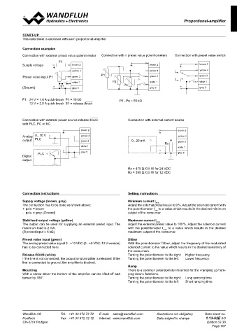
Connection examples
Connection with external preset value potentiometer Connection with n preset value potentiometers Connection with preset value switch
F1 F1
F1
F1 F1
brown 2
brown 2
brown 2
brown 2
Supply voltage
brown 2
brown 2
brown 2
Supply voltage
Supply voltage
brown 2
brown 2
brown 2
brown 2
Supply voltage
Supply voltage brown 2 + ++ + + brown 2 + ++ + + brown 2
brown 2
+ ++ + +
yellow 4
yellow 4
yellow 4
yellow 4
yellow 4
yellow 4
yellow 4
yellow 4
yellow 4
yellow 4
yellow 4
yellow 4
yellow 4 yellow 4 I maxmax yellow 4
I max I I max
I max
P1
P1 P1
green 3
green 3
green 3
green 3
green 3
green 3
green 3
Preset value input P1
green 3
green 3
green 3
Preset value input P1 green 3 P1 P1 green 3 I I min green 3
green 3
Preset value input P1
Preset value input P1
green 3
Preset value input P1
I min I min
P2 P2
P2
white 1
white 1
white 1
white 1
white 1
white 1
white 1
white 1
white 1
white 1
white 1
white 1 P2 P2 Pn Pn white 1 I min min white 1
white 1
Pn
S1 S1
S1
(Ground)
(Ground) - - - - - S1 S1 grey 5 Pn Pn grey 5 - - - - - grey 5
(Ground)
(Ground)
(Ground)
grey 5
grey 5
grey 5
grey 5
grey 5
grey 5
grey 5
grey 5
grey 5
grey 5
grey 5
grey 5
F1: 24 V = 1,6 A quick-break P1 = 10 kΩ P1 – Pn = 50 kΩ
12 V = 2,5 A quick-break S1 = release / block
Connection with external power source release / block Connection with external current source
with PLC, PC or NC
brown 2
brown 2
brown 2
brown 2
brown 2
brown 2
brown 2
brown 2
+ ++ + + brown 2 + ++ + + brown 2
0...10 V
0...10 V
0...10 V
0...10 V
Analog
yellow 4
yellow 4
Analog
Analog
yellow 4
yellow 4
yellow 4
yellow 4
yellow 4
yellow 4
Analog 0...10 V yellow 4 yellow 4
Analog
PLC
PLC
PLC
PLC
output
output
output
output
output PLC green 3 0...20 mA green 3
0...20 mA
0...20 mA
0...20 mA
0...20 mA
green 3
green 3
green 3
green 3
green 3
green 3
green 3
Rx Rx
Rx
Rx Rx green 3
white 1
white 1
white 1
white 1
white 1 white 1
white 1
white 1
white 1
- - - - - - - - - - white 1
grey 5
grey 5
grey 5
grey 5
grey 5
grey 5
grey 5
PLC
PLC
grey 5
PLC grey 5 grey 5
PLC
PLC
Digital
Digital
Digital
Digital
Digital
output
output
output
output
output
Rx = 470 Ω / 0,5 W for 24 VDC
Rx = 390 Ω / 0,5 W for 12 VDC
Connection instructions Setting instructions
Supply voltage (brown, grey) Minimum current I min
The connection has to be done as shown above: Adjust the external preset value to 0 %. Adjust the solenoid current with
+ pole = brown the potentiometer I to a value which results in the desired minimum
min
- pole = grey (Ground) output of the consumer.
Stabilized output voltage (yellow) Maximum current I max
The output can be used for supplying an external preset input. The Adjust the external preset value to 100 %. Adjust the solenoid current
maximum load is 2 mA. with the potentiometer I max to a value which results in the desired
(R preset input ≥ 5 kΩ) maximum output of the consumer.
Preset value input (green) Dither
The analog preset value signal 0...+10 VDC (0...+8 VDC / 12 V-version) With the potentiometer Dither, adjust the frequency of the modulated
has to be connected here. solenoid current to the value which results in the desired sensitivity of
the consumers.
Release / block (white) Turning the potentiometer to the right: Higher frequency.
If the line is not connected, the proportional amplifier is released. If the Turning the potentiometer to the left: Lower frequency.
line is connected to ground, the amplifier is blocked.
Ramp
Mounting There is a common potentiometer mounted for the «ramping up / ram-
With a screw driver the bottom of the amplifier can be lifted-off and ping down» functions.
turned by 180°. Turning the potentiometer to the right: Long ramping time.
Turning the potentiometer to the left: Short ramping time.
Wandfluh AG Tel. +41 33 672 72 72 E-mail: [email protected] Illustrations not obligatory Data sheet no.
Postfach Fax +41 33 672 72 12 Internet: www.wandfluh.com Data subject to change 1.13-62E 3/3
CH-3714 Frutigen Edition 03 38
Page 707