
Page 715 - Softbound_Edition_19_en
P. 715
2
1
(1 : 1)
18.5
2x M3
F
F
F
X1-1
A
X1-5
spannung
X1-5
X1-5
d'alimentation
gray
voltage
grau
18.5 3 4 51 5 28.7 19.25 A Versorgungs- F = Sicherung träge braun Supply F = Fuse slow X1-1 brown Tension F = Sécurité inerte X1-2
USB/PASO USB/PASO USB/PASO
Digital amplifier electronics
51 Digital amplifier electronics PD2 Digital amplifier electronics PD2
19.25 0...1 VDC 0...1 VDC 0...1 VDC
DIMENSIONS PD2 AMPLIFIER WITH CANopen INTERFACE X1-3 weiss 6...32 VDC X1-3 white 6...32 VDC X1-3 blanc
6...32 VDC
28.7
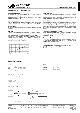
B 51 B Command value scaling Signal recording
The command value can be applied as a CAN-bus-, digital, frequency Furthermore, the „PD2“ amplifier electronics have a signal recording
Adapter
USB/PASO
18.5 6.25 or PWM signal. The scaling takes place via the parameter „Interface”. function. This, by means of PASO, enables the recording of various sy-
USB-PD2
Furthermore, the command value can be monitored for a cable break. stem signals, such as command value, solenoid current, etc., which
A dead band can also be set.0...1 VDC can be represented on a common time axis.
6...32 VDC X1-3 weiss
19.25 Fixed command value Solenoid driver
1.5 17 28.7 There is 1 fixed command value available, which can be selected via A Pulse-Width-Modulated current output is available. A dither signal
the digital input. This function has to be configurated before in PASO.
is superimposed, whereby the dither frequency and the dither level
1 brown are separately adjustable. The minimum (Imin) and maximum (Imax)
2 green Ramp generator current can be adjusted. The solenoid output can also be configurated
3 white Two linear ramps for up and down are available which can be adjusted as switching solenoid output. In this case, a power reduction can be
19.25 4 yellow 3.3 separately. X1-4 adjusted. X1-4 X1-4
C 5 grey C gelb yellow jaune
6.1 Valve type X1-2 Optimisation of characteristic curve X1-2
X1-2
grün
green
Adjustment possibilities: switching solenoid or proportional solenoid. An adjustable characteristic curve „Command value input – solenoid vert
grey
X1-5
X1-5
CONNECTOR ASSIGNMENT X1-5 grau current output“ enables an optimised (e.g. linearised) characteristic of gris
Connection cable (X1) Solenoid cable (X2) Mode of operation „Command value unipolar/bipolar (1-Sol) the hydraulic system.
Dependent on a command value signal (CAN-bus, digital, frequency
1 brown 1 brown or PWM), the solenoid is driven (e.g. 0….16383 CAN-command cor- Channel enabling
2 green respond to 0….100 % command value, 0….+100 % command value As per factory setting, the device can be enabled via CAN-bus. This
3 white correspond to Imin….Imax solenoid driver) „enable channel“ can be set to „bus“, „on“, „off“ or „external“ (digital
4 yellow input) via PASO or via menu item.
5 grey 2 white
1 = + VCC 1 = Solenoid +
2 = CAN-Low 02 02.11.2015 BEH Ansicht für Befestigungsbohrungen hinzugefügt Gezeichnet 22.08.2014 ZUA Important! Digital input: If deenergised, the state
2 = Solenoid -
3 = Dig Inp 03 28.03.2017 BEH Massstab 1:1 - Format A3 Geprüft 21.07.2020 SMI of the digital input is not defined
D 4 = CAN-High 04 01.07.2020 SMI Bemassung Langlöcher geändert Freigegeben 21.07.2020 TK D
1 brown
5 = GND Rev. Datum Name Änderungsnr. Änderungsbeschrieb ADDITIONAL INFORMATION M 1:1 Serie freigegeben 0...10 VDC X1-2 grün 0...10 VDC X1-2 green 0...10 VDC X1-2 vert
+/-10 VDC
X1-5
X1-5
X1-5
+/-10 VDC
+/-10 VDC
grey
gris
grau
Gewicht
Ersetzt durch:
Steckerverstärker
0.018 kg
START-UP Ersatz für: Wandfluh documentation-
Dok.-Nr.
Format
PD2301D80-AA
register
A3
Information regarding installation and commissioning are contained in Wandfluh electronics general 0158797 1.13
the information leaflet supplied with the amplifier electronics and in the Art.-Nr. Revision 0 % 100 % Command value
2 white
Dokument darf ohne schriftliche Einwilligung weder kopiert,
register
Proportional spool valve
04
operating instructions. verwertet noch an Dritte weitergegeben werden. DB 1.13-64 1.10 5 Hz 5000 Hz
Zuwiderhandlung ist strafbar und wird gerichtlich verfolgt.
0 Inc 16383 Inc Bus command value
2.3
Proportional pressure valves
register
1 2 C:\00_Wandfluh\Artikelhierarchie\01_Verkaufsartikel\26_Elektronik\11_Verstärker\0158797 Blatt 1 von 1
Additional information can be found on our website: Proportional flow control valves register 2.6
«www.wandfluh.com» 0...20 mA X1-2 grün 0...20 mA X1-2 green 0...20 mA X1-2 vert
4...20 mA X1-5 grau 4...20 mA X1-5 grey 4...20 mA X1-5 gris
Free-of-charge download: ACCESSORIES CONNECTION EXAMPLES
• «PASO-PD2» Parameterisation software USB-adapter PD2 Article no. 726.9900
• Operating instruction (*.pdf) incl. USB-cable, type A-B, 1,8 m Supply voltage CAN connection
(for parameterisation via PASO) Versorgungs- F X1-1 braun Supply F X1-1 brown Tension F X1-2
F
spannung
d'alimentation
gray
X1-2
Versorgungs- F X1-1 X1-5 grau Supply voltage CAN-Low X1-1 X1-5 brown X1-2 grün Tension CAN-Low F X1-2 X1-5 green CAN-Low X1-2 vert
braun
X1-5
X1-5
X1-5
ADJUSTMENTS spannung F = Sicherung träge grau voltage F = Fuse slow gray X1-4 d'alimentation F = Sécurité inerte CAN-High X1-4
X1-4
CAN-High
CAN-High
The PD2 electronics have push-buttons and a 7 segment display which enable setting the most important parameters. In addition, the digital F = Fuse slow gelb F = Sécurité inerte yellow jaune
F = Sicherung träge
input can be used as a communication interface, through which, by means of the parameterisation software „PASO-PD2“, the complete para-
meterisation and diagnostics can be carried out. For this, the Wandfluh USB-PD2 adapter is required. (not included in the delivery)
Important: During the communication, the digital input cannot be used. Digital input as function input
USB/PASO USB/PASO USB/PASO
USB/PASO USB/PASO USB/PASO
FUNCTION DESCRIPTION 0...1 VDC X1-3 weiss 0...1 VDC X1-3 white 0...1 VDC X1-3 blanc
6...32 VDC
6...32 VDC
6...32 VDC
0...1 VDC 0...1 VDC 0...1 VDC
6...32 VDC X1-3 weiss 6...32 VDC X1-3 white 6...32 VDC X1-3 blanc
Adapter
USB/PASO Adapter
USB-PD2
USB/PASO USB-PD2 Digital input as USB interface
Command Solenoid output 0...1 VDC VCC
value Command Fixed Ramp Solenoid
scaling command generator Valve type 0...1 VDC X1-3 weiss
6...32 VDC
values driver Current measurement X1-3 weiss brown
6...32 VDC VCC+
PC USB USB - Adapter ON DIG white
PASO TX DigInp PD2
DigInp DigInp DigInp DigInp RX OV grey GND
Error Number Enable Solenoid Enable Error GND
X1-4 gelb X1-4 yellow X1-4 jaune
X1-4
X1-4 gelb X1-4 yellow USB type B Screwterminal jaune
X1-2 grün X1-2 green X1-2 vert
X1-2 grün X1-2 green X1-2 vert
X1-5 grau X1-5 grey X1-5 gris
Wandfluh AG Tel. +41 33 672 72 72 E-mail: [email protected] Illustrations not obligatory X1-5 Data sheet no. X1-5 Wandfluh AG Tel. +41 33 672 72 72 gris Illustrations not obligatory Data sheet no.
E-mail: [email protected]
grau
grey
X1-5
Postfach Fax +41 33 672 72 12 Internet: www.wandfluh.com Data subject to change 1.13-64E 6/7 Postfach Fax +41 33 672 72 12 Internet: www.wandfluh.com Data subject to change 1.13-64E 7/7
CH-3714 Frutigen Edition 21 20 CH-3714 Frutigen Edition 21 20
Page 715
0...10 VDC X1-2 grün 0...10 VDC X1-2 green 0...10 VDC X1-2 vert
+/-10 VDC
+/-10 VDC
+/-10 VDC
vert
grün
green
0...10 VDC X1-2 X1-5 grau 0...10 VDC X1-2 X1-5 grey 0...10 VDC X1-2 X1-5 gris
+/-10 VDC X1-5 grau +/-10 VDC X1-5 grey +/-10 VDC X1-5 gris
0...20 mA X1-2 grün 0...20 mA X1-2 green 0...20 mA X1-2 vert
4...20 mA
4...20 mA
4...20 mA
vert
0...20 mA X1-2 X1-5 grau 0...20 mA X1-2 X1-5 grey 0...20 mA X1-2 X1-5 gris
green
grün
4...20 mA X1-5 grau 4...20 mA X1-5 grey 4...20 mA X1-5 gris
CAN-Low X1-2 grün CAN-Low X1-2 green CAN-Low X1-2 vert
CAN-Low X1-2 grün CAN-Low X1-2 green CAN-Low X1-2 vert
CAN-High X1-4 gelb CAN-High X1-4 yellow CAN-High X1-4 jaune
CAN-High X1-4 gelb CAN-High X1-4 yellow CAN-High X1-4 jaune