
Page 719 - Softbound_Edition_19_en
P. 719
2
1 2 A 1 2x M3 3 18.5 4 18.5 3 5 51 4 5 A
28.7
18.5 19.5
Digital amplifier electronics PD3 Digital amplifier electronics PD3
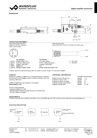
Digital amplifier electronics
ELECTRICAL SPECIFICATIONS Dither 2x M3 B DIMENSIONS B
Protection class IP 67 acc. to EN 60 529 A Frequency adjustable 4…500 Hz A 19.25
Supply voltage IO-Link: 24 V (18..30V), analogue: 8..32V Factory setting 80 Hz 51
Residual ripple < 1.3 Vpp Level adjustable 0…400 mA
Fuse Low Factory setting 180 mA 18.5 18.5 6.25
No-load current Approx. 30 mA Temperature drift <1 % bei ∆T = 40 °C
Max. current Enable input 1 input high-active
consumption No-load current + 2,5 A per solenoid Switching threshold high 1/2 VCC +2V
Command value input 1 input non-differential Switching threshold low 1/2 VCC -2V
Voltage / current (switchable by means of parameter) Ramps Adjustable 0…500 s
0...+ 10V or 0/4...20mA IO-Link interface Data line C/Q, COM2 = 38,4 kBaud 19.5 1.5 17 28.7
Usable as frequency input Use master type B
(frequency 5...5000 Hz) or as PWM input Bluetooth Low Energy with access protection
(automatic frequency detection) or digital Contains FCC ID: QOQ11 C
dig. switching threshold high >3V Fieldbus (option) CANopen (on request) 1 brown 3.3
B
dig. switching threshold low <0.8V J1939 (on request) 2 green B
Resolution 12-bit LEDs Function green 3 white 6.1
Input resistance Voltage input >100 kΩ Bluetooth blue 51 4 yellow
Load for current input = 124 Ω IO-Link green CONNECTOR ASSIGNMENT 5 grey
Stabilised output 5 VDC Error red Valve connection cable (X1) 18.5 6.25 Solenoid cable (X2)
voltage max. load 20 mA Supply solenoid with IO-Link With mounted M12 connector Open end for free choice of the valve connection plug
Solenoid current: galvanically separated via P24/N24 5-pole male A coded
• Minimal current I Adjustable 0…I max mA EMV 2014/53/EU (Radio Equipment Directive)
min
Factory setting 50 mA ETSI EN 300 328 2 1 1 brown
Adjustable I …2500 m A 47 CFR, Part 15 / ICES-003
• Maximal current I max min 5 1.5 17 28.7
Factory setting 700 mA ETSI EN 301 489-1 / 301 489-17 Gezeichnet 20.02.2019 BEH
Immunity EN 61 000-6-2 3 4 Geprüft 21.07.2020 FA
Emission EN 61 000-6-4 D 01 01.07.2020 SMI Bemassung Langlöcher geändert 2 white 21.07.2020 TK
Freigegeben
BLOCK DIAGRAM C Rev. Datum Name Änderungsnr. Änderungsbeschrieb M 1:1 Serie freigegeben Modellreferenz: Doknr. 0247162 / Konfiguration 002
Gewicht
Steckerverstärker
Typ analogue 3.3 Typ I/O-Link Ersetzt durch: 0.017 kg
Ersatz für:
1 (brown) Supply voltage VCC + L+ supply voltage + 1 = Solenoid + Dok.-Nr. Format
PD3401D80-AI
X2-1 2 (green) Command value signal 6.1 P24/2L+ additional supply + 2 = Solenoid - 0247390 A3
3 (grey) Supply 0 VDC/GND L-supply 0 VDC/GND Dokument darf ohne schriftliche Einwilligung weder kopiert, Art.-Nr. Revision
4 (white) Digital input C/Q verwertet noch an Dritte weitergegeben werden. DB 1.13-66 01
Zuwiderhandlung ist strafbar und wird gerichtlich verfolgt.
1 5 (yellow) 2 Stabilised output voltage* N24/2L-additional supply 0 VDC C:\00_Wandfluh\Verkauf\Dokumentation\Reg1.13\DB 1.13-66\0247390 Blatt 1 von 1
*Caution: Some M12 distributor boxes have the earth connection on pin 5 Short-circuit hazard!
M12
Modellreferenz: Doknr. 0247162 / Konfiguration 002
Connector pins
START-UP ADDITIONAL INFORMATION
Information regarding installation and commissioning are contained in Wandfluh documentation
Gezeichnet 20.02.2019 BEH
the information leaflet supplied with the amplifier electronics and in the
21.07.2020
FA
1 L+ Internal Supply Solenoid 01 01.07.2020 SMI Bemassung Langlöcher geändert Geprüft Wandfluh electronics general register 1.13
TK
21.07.2020
Freigegeben
D
supply PWM operating instructions. Proportional spool valves register 1.10
Serie freigegeben
Rev. Datum Name Änderungsnr. Änderungsbeschrieb M 1:1 Proportional pressure valves register 2.3
Gewicht
Steckerverstärker Ersetzt durch: Proportional flow control valves register 2.6
Additional information can be found on our website:
0.017 kg
Ersatz für:
Solenoid coil with PD3
register
1.1-331
www.wandfluh.com
PD3401D80-AI Dok.-Nr. 0247390 Format
A3
Dig
A/D Free-of-charge download: Art.-Nr. Revision
Dokument darf ohne schriftliche Einwilligung weder kopiert,
• Operating instruction (*.pdf) DB 1.13-66 01
verwertet noch an Dritte weitergegeben werden.
I: P24 Zuwiderhandlung ist strafbar und wird gerichtlich verfolgt.
C:\00_Wandfluh\Verkauf\Dokumentation\Reg1.13\DB 1.13-66\0247390
1 2 • Wandfluh App for Android (Google Play) and iOS (App Store) Blatt 1 von 1
2 A: Command U/I/D *1) X2-2 • IO-Link Interface Description
A/D
C/J: CAN_Low
ADJUSTMENTS
The PD3 electronics has a Bluetooth interface. Via the Wandfluh App, the PD3 functions can be analysed and all parameters set.
3 L- CAN
4 I: IO-Link C/Q Rx/Tx FUNCTION DESCRIPTION
A/C/J: Enable
Command Solenoid output
value Command Ramp Solenoid
A: Stab.Out scaling generator Valve type driver
5 I: N24 *1) BLE 4x Current measurement
FLASH
C/J: CAN_High RAM
Error Error
*1) fix selection according to type code
Wandfluh AG Tel. +41 33 672 72 72 E-mail: [email protected] Illustrations not obligatory Data sheet no. Wandfluh AG Tel. +41 33 672 72 72 E-mail: [email protected] Illustrations not obligatory Data sheet no.
Postfach Fax +41 33 672 72 12 Internet: www.wandfluh.com Data subject to change 1.13-66E 2/4 Postfach Fax +41 33 672 72 12 Internet: www.wandfluh.com Data subject to change 1.13-66E 3/4
CH-3714 Frutigen Edition 21 20 CH-3714 Frutigen Edition 21 20
Page 719