
Page 224 - Softbound_Edition_19_en
P. 224
Solenoid operated spool valve
Solenoid operated spool valve Solenoid operated spool valve
DIMENSIONS Solenoid operated spool valve with soft switching
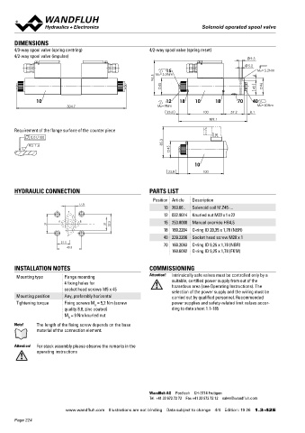
4/3-way spool valve (spring centring) 4/2-way spool valve (spring reset) Flange construction NG4-Mini
4/2-way spool valve (impulse) Wandfluh standard
9.5 ◆ 4/3-way with spring centred mid position
5.2 ◆ 4/2-way with spring reset
15 MD= 5.2Nm ◆ Q = 20 l/min
max
94.5 MD=5.5Nm 6 ◆ p = 350 bar
max
45 46
40
10 12 18 10 18 70 40 DESCRIPTION APPLICATION
304.7 MD=9Nm MD=50Nm Direct operated solenoid spool valve with 4 connections in 5 cham- Normal solenoid spool valves switch very quickly. This can lead to
23.8 100 57.2 8.1 ber design. With the solenoids deenergised, the spool is held in the shocks in the hydraulic system which can cause mechanical wear
189.1 center position by the spring (4/3), or switched back to the offset and have a negative effect on operation. The soft switching valves
position (4/2). The soft switching of the valve is achieved by means slow down and dampen the switching movements which benefits
Requirement of the flange surface of the counter piece of an optimum combination of the orifice and spool design. Precise the system. Optimum results can be achieved if all 4 connections
0.01/100 spool fit, low leakage, long service life time. Spool made from are connected and the valve is properly vented. Miniature values
Ra 1.6 85.3 hardened steel, valve body from high quality hydraulic cast steel. are used where both, reduced dimensions and weight are import-
45 Wide range of standard and special voltages. ant.
10 SYMBOL
23.8 100
AB1 AB2
A B
HYDRAULIC CONNECTION PARTS LIST a b a b
Position Article Description a b a b
17.8 P T
10 263.66.. Solenoid coil M.Z45-...
T ACB AC1 CB2
12 032.9614 Knurled nut M22 x 1 x 22
A B A B A B
A B 15 253.8000 Manual override HB4,5
31 21 32.5
18 160.2204 O-ring ID 20,35 x 1,78 (NBR) a 0 b a b
P a b a b
40 239.2206 Socket head screw M20 x 1
21.5 70 160.2093 O-ring ID 9,25 x 1,78 (NBR) P T P T P T
40.5 ADB AD1 DB2
160.6092 O-ring ID 9,25 x 1,78 (FKM)
A B A B A B
0
INSTALLATION NOTES COMMISSIONING a a b b a a b b
Mounting type Flange mounting Attention! Intrinsically safe valves must be controlled only by a P T P T P T
4 fixing holes for suitable, certified power supply from out of the
socket head screws M5 x 45 hazardous area (see Operating Instructions). The
selection of the power supply and the wiring must be
Mounting position Any, preferably horizontal carried out by qualified personnel. Recommended GENERAL SPECIFICATIONS HYDRAULIC SPECIFICATIONS
Tightening torque Fixing screws M = 5,2 Nm (screw power supplies and safety-related limit values accor- Designation 4/2-, 4/3-spool valve Working pressure p = 350 bar (p < 20 bar)
D
T
max
quality 8.8, zinc coated) ding to data sheet 1.1-185 Construction Direct operated p = 315 bar (p > 20 bar)
M = 9 Nm knurled nut max T
D Mounting Flange construction Tank pressure p T max = 100 bar
Note! The length of the fixing screw depends on the base Nominal size NG4-Mini according to Wandfluh Maximum volume flow Q = 20 l/min, see characteristics
max
material of the connection element. standard Leakage oil See characteristics
Actuation Switching solenoid Fluid Mineral oil, other fluid on request
2
2
Attention! For stack assembly please observe the remarks in the Ambient temperature -25…+70 °C Viscosity range 12 mm /s…320 mm /s
operating instructions if > +50 °C, then no undervoltage is Temperature range -25…+70 °C (NBR)
admissible fluid -20…+70 °C (FKM)
Weight 0,90 kg (1 solenoid) Contamination Class 18 / 16 / 13
1,25 kg (2 solenoids) efficiency
MTTFd 150 years Filtration Required filtration grade ß 10…16 ≥ 75,
see data sheet 1.0-50
Wandfluh AG Postfach CH-3714 Frutigen
Tel. +41 33 672 72 72 Fax +41 33 672 72 12 [email protected]
www.wandfluh.com Illustrations are not binding Data subject to change 4/4 Edition: 19 26 1.3-42 E www.wandfluh.com Illustrations are not binding Data subject to change 1/4 Edition: 22 13 1.4-13 E
Page 224