Page 377 - Softbound_Edition_19_en
P. 377

Proportional spool valve
                                                                                           Proportional spool valve


            ELECTRICAL CONNECTION
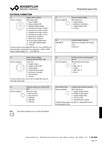
             X1                 Analog interface (Main)           X1                 Fieldbus interface (Main)
             Device receptacle  M23, 12 pole male                 Device receptacle  M12, 4 pole male
                                1 = Supply voltage +                           2  1  1 = Supply voltage +
                       8 9  1   2 = Supply voltage 0 VDC                             2 = Reserved for extentions
                      7 12 10 2  3 = Stabilised output voltage                 3 4   3 = Supply voltage 0 VDC
                      6  11 3
                        5  4    4 = Command value signal voltage +                   4 = Chassis
                                5 = Command value signal voltage -
                                6 = Command value signal current +
                                7 = Command value signal current -
                                8 = Reserved for extentions
                                9 = Reserved for extentions
                                10 = Enable signal (Digital input)  X2               Parameterisation interface
                                11 = Error signal (Digital output)  USB, Mini B      Under the screw plug of the housing
                                12 = Chassis                                         cover
             Command value signal voltage (PIN 4/5) resp. current (PIN 6/7) are      Factory set
             selected with parameterisation and diagnostics  software PASO.
             Factory setting: voltage (-10… +10 V), (PIN 4/5)


             X1                 Analog interface (Main)           X3                 Profibus interface according to IEC
                                Connector DIN EN 175201 - 804                        947-5-2
             Device receptacle  7 pole male                       Device receptacle  M12, 5 pole female B-coded
                                A = Supply voltage +                           2 3   1 = VP
                         A                                                     5
                     F     B    B = Supply voltage 0 VDC                       1 4   2 = RxD / TxD - N
                         G      C = Analog output -                                  3 = DGND
                     E     C
                         D      D = Command value signal +                           4 = RxD / TxD - P
                                E = Command value signal -                           5 = Shield
                                F = Analog output +
                                G = Chassis
             Command value signal: current (D4) or voltage (D2) to specify
             when placing the order


             X3                 CANopen interface according to DRP   X4 (controller only)  Feedback value interface (sensor)
                                303-1                             Device receptacle  M12, 5 pole female
             Device receptacle  M12, 5 pole male                               2 3   1 = Supply voltage (output) +
                                1 = Not connected                              5     2 = Feedback value signal +
                          2 1                                                  1 4
                           5    2 = Not connected                                    3 = Supply voltage 0 VDC
                          3 4
                                3 = CAN Gnd                                          4 = Not connected
                                4 = CAN High                                         5 = Stabilised output voltage
                                5 = CAN Low                       Feedback value signal: current (R1) or voltage (R2) to specify
                                                                  when placing the order


            Note!    The mating connector is not included in the delivery


                               www.wandfluh.com  Illustrations are not binding  Data subject to change  3/6  Edition: 18 12  1.10-82 E
                                                                                                            Page 377
   372   373   374   375   376   377   378   379   380   381   382