Page 444 - Softbound_Edition_19_en
P. 444

Proportional spool valve
                                                                                     Proportional spool valve                                                                                                     Proportional spool valve


       PERFORMANCE SPECIFICATIONS                                                                                                  DIMENSIONS
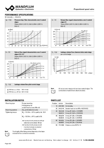
       Oil viscosity u = 30 mm /s                                                                                                  4/3-way spool valve (spring centring)
                       2
       ∆p = f (Q)  Pressure drop / flow characteristic over 2 control   Q = f (I)  Volume flow signal characteristics over 2 control                        227
                  edges                                               edges L9                                                                              57.2                                         45
                  [Types: BCA-S, BC1-S, CA2-S, BDA-V, BD1-V,          [Types: BCA-S, BC1-S, CA2-S, BDA-V, BD1-V,
                  DA2-V]                                              DA2-V]
          ∆p [bar]                                              Q [l/min]
                                      L9      L15                                             100,~200 bar
            K4128                                                K4241                                                                                 60  20  80
                                                              200
         40
                                                              160                                    50 bar
         30                                                                                          30 bar
                                                              120
         20                                                    80                                    20 bar
                                                                                                     10 bar
         10                                                    40                                                                         a                                  b                                          171
          0                                                    0                                      I [%]
           0  20  40  60  80  100 120  140  160 180 200  Q [l/min]  20  30  40  50  60  70  80  90  100                                                                         MD=9Nm  MD=5.5Nm

                                                                                                                                        35
       Q = f (I)  Volume flow signal characteristics over 2 control   Q  = f (p)  Leakage volume flow characteristics main stage                                                                                     69
                                                             L
                  edges L15 / L17                                     per control edge
                  [Types: BCA-S, BC1-S, CA2-S, BDA-V, BD1-V,    Q [ml]                                                                                                            29
                  DA2-V]                                     400  K2092
                                                             350                                                                              10   40    30     6.5
           Q [l/min]                                         300                                                                                                10.5                                     68
         200  K4129                 100,~200 bar  50 bar     250
                                                             200                                                                                27           93
         160                                    30 bar       150                                                                                            147
         120                                    20 bar       100                                                                   Dimensions of the solenoid coil, refer to data sheet 1.1-183 and 1.1-184
                                                10 bar        50
          80                                                   0
                                                                 0   50   100  150  200  250  300  350 p [bar]                     4/2-way with spring reset                            HYDRAULIC CONNECTION
          40                                                                                                                                       149.4

           0                                                                                                                                                                                                      93
           20   30  40   50  60   70  80  90  100  I [%]
                                                                                                                                                                                                                 70.8
                                                                                                                                                                                                                  54
                                                                                                                                                                                                                P
       Q  = f (p)  Leakage volume flow pilot control stage                                                                                                                                                X             Y
         L                                                                                                                                                                                               12   A     B        16.8
                                                                                                                                                                                                      68    T         To   1.5    46
                                                           Note!    All values were measured over two control edges. The                                                                                                     9.7
         @ 350 bar, pred 0 bar:   100 ml/min                        connections A and B were short-circuited.
         @ 350 bar, pred 25 bar: 320 ml/min                                                                                                                                                                      20.8
                                                                                                                                          a                                        171.4                          48
                                                                                                                                                                                12
       INSTALLATION NOTES                                  PARTS LIST

       Mounting type      Flange mounting                    Position Article  Description
                          4 fixing holes for                     10 239.7203  Screw plug
                          socket head screws M6 x 40             20 246.2146  Socket head screw M5 x 45 DIN 912
       Mounting position  Any, preferably horizontal
       Tightening torque  M  = 13.5 Nm ± 10 %, quality min. 10.9  30 160.2120  O-ring ID 12,42 x 1,78 (NBR)
                            D                                       160.8124  O-ring ID 12,42 x 1,78 (FKM)                                              187
                          M  = 10.5 Nm ± 10 %, quality 8.8:      40 160.2076  O-ring ID 7,65 x 1,78 (NBR)
                            D
                                                                    160.8076  O-ring ID 7,65 x 1,78 (FKM)
                           ◆  maximum tank pressure without      60 160.2052  O-ring ID 5,28 x 1,78 (NBR)
                            external connections: 80 bar            160.6052  O-ring ID 5,28 x 1,78 (FKM)
                           ◆  maximum tank pressure and          80 173.1450  Distance plate BDP4 / 12
                            maximum pressure external
                            connections: 35 bar
       Note!   The length of the fixing screw depends on the base
               material of the connection element.                                                                                                                                      Wandfluh AG  Postfach  CH-3714 Frutigen
                                                                                                                                                                                        Tel. +41 33 672 72 72  Fax +41 33 672 72 12  [email protected]

                       www.wandfluh.com  Illustrations are not binding  Data subject to change  4/5  Edition: 21 18  1.10-3520 E                   www.wandfluh.com  Illustrations are not binding  Data subject to change  5/5  Edition: 21 18  1.10-3520 E
       Page 444
   439   440   441   442   443   444   445   446   447   448   449