
Page 440 - Softbound_Edition_19_en
P. 440
Proportional spool valve
Proportional spool valve Proportional spool valve
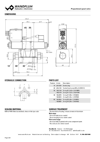
DIMENSIONS Proportional spool valve
Flange construction NG10
215.4 ISO 4401-05
◆ pilot operated
57.2 67.7 6.2 ◆ Q = 200 l/min x II 2 G Ex db IIC T6, T4
max
38 ◆ Q N max = 90 l/min x II 2 D Ex tb III C T80 °C, T130 °C
◆ p = 350 bar x I M2 Ex db I Mb
max
60 20 Class I Division 1
X2 Class I Zone 1
X1
DESCRIPTION APPLICATION
Pilot operated proportional spool valve with 4 connections in These valves are suitable for applications in explosion-hazard
X3
5-chamber system. Very compact construction with corresponding areas, open cast and also in mines. Pilot operated valves are used
low weight and high flow values. The function of the pilot and main where large volume flows have to be controlled. Due to the large
valve as well as the interaction of both valves can be found in the flow range and the high stiffness of the actuation as a result of the
171.5 hydraulic diagram. Proportional to the solenoid current, the spool pilot control, these valves are suitable for applications where fast
stroke, the spool opening and the valve volume flow increase. The
acceleration and deceleration processes, high speeds and sensi-
pressure tight encapsulated Ex-protection solenoid coil prevents tive motion sequences are required. The applications are in the
an explosion on the inside penetrating to the outside as well as an industrial as well as in the mobile hydraulics for the smooth control
MD=5Nm
ignitable surface temperature. For the control, Wandfluh proporti - of hydraulic actuations.
35 69.6 onal pressure valves (see register 2.3) and Wandfluh proportional
amplifiers (see register 1.13) are available.
29
10 40 30 6.5 68
CERTIFICATES ACTUATION
10.5
Surface Mining Standard M248 Pressure reducing valve
26.9 93.2 -25 °C Electronic MDBFA04-P / AB-25 for BCA-S / BDA-V
147 to… MDBFA04-P / B-25 for BC1-S / BD1-V
MDBFA04-P / A-25 for CA2-S / DA2-V
ATEX x x x x
HYDRAULIC CONNECTION PARTS LIST IECEx x x x x Attention! The UL execution is always supplied without cable
gland
Position Article Description CCC x x x x
54 EAC x x x x
10 239.7203 Screw plug
P Australia x x x
20 246.2146 Socket head screw M5 x 45 DIN 912
MA x x x
1.5
A B 16.8 30 160.2120 O-ring ID 12,42 x 1,78 (NBR)
46 UL / CSA x x
9.7 160.8124 O-ring ID 12,42 x 1,78 (FKM)
T To 40 160.2076 O-ring ID 7,65 x 1,78 (NBR) The certificates can be found on www.wandfluh.com
160.8076 O-ring ID 7,65 x 1,78 (FKM)
20.8
60 160.2052 O-ring ID 5,28 x 1,78 (NBR) SYMBOL
24
160.6052 O-ring ID 5,28 x 1,78 (FKM) Symmetrical control
BCA-S BC1-S CA2-S
A B A B A B
SEALING MATERIAL SURFACE TREATMENT a 0 b a b
NBR or FKM (Viton) as standard, choice in the type code -The electronics housing / chassis is made of aluminium a b a b
Main stage: P T P T P T
-The valve body is zinc coated Meter-in control
-The screw plug is zinc-nickel coated BDA-V BD1-V DA2-V
Pilot control stage: A B
-The valve body is painted with a two component paint A B A B
-The coils are zinc-nickel coated a 0 b a b
a b a b
P T P T P T
Wandfluh AG Postfach CH-3714 Frutigen
Tel. +41 33 672 72 72 Fax +41 33 672 72 12 [email protected]
www.wandfluh.com Illustrations are not binding Data subject to change 6/6 Edition: 18 41 1.10-3510 E www.wandfluh.com Illustrations are not binding Data subject to change 1/5 Edition: 21 18 1.10-3520 E
Page 440