Page 437 - Softbound_Edition_19_en
P. 437
Proportional spool valve
                                                                                           Proportional spool valve


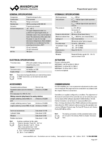
            GENERAL SPECIFICATIONS                               HYDRAULIC SPECIFICATIONS
             Designation        Proportional spool valve          Working pressure   p  = 350 bar
                                                                                     max
             Construction       Pilot operated                    Tank pressure      p    = 160 bar (type of pilot operation
                                                                                     T max
             Mounting           Flange construction                                  ae and xi)
             Nominal size       NG10 according to ISO 4401-05                        p T max  = 100 bar (type of pilot operation ti
             Actuation          Proportional solenoid                                and xe)
             Ambient temperature  -20…+65 °C                      Pilot pressure     p  = 25...350 bar
                                                                                     v
                                The upper temperature limit is a                     Connection X:
                                guideline for typical applications, in               p  = 25...200 bar
                                                                                     v
                                individual cases it may also be higher or   Pressure pilot oil drain  Minimum 25 bar lower than p v
                                lower. The electronics of the valve limit   Maximum volume flow  Q  max  = 200 l/min, see characteristics
                                the power in case of a too high   Leakage oil        See characteristics
                                electronics temperature. More detailed   Fluid       Mineral oil, other fluid on request
                                information can be obtained from the   Viscosity range  12 mm /s…320 mm /s
                                                                                                  2
                                                                                         2
                                operating instructions „DSV”.     Temperature range   -25…+70 °C (NBR)
             Weight             3,5 kg (1 solenoid)               fluid              -20…+70 °C (FKM)
                                3,9 kg (2 solenoids)              Contamination      Class 18 / 16 / 13
             MTTFd              150 years                         efficiency
                                                                  Filtration         Required filtration grade ß 6…10 ≥ 75,
                                                                                     see data sheet 1.0-50

            ELECTRICAL SPECIFICATIONS                            ACTUATION
             Protection class   IP67 with suitable mating connector and   Pressure reducing valve
                                closed housing cover             MDPFA04-P / AB-25 for BCA-S / BDA-V
             Ramps              Adjustable                       MDPFA04-P / A-25 for BC1-S / BD1-V
             Parameterisation   Via fieldbus or USB              MDPFA04-P / B-25 for CA2-S / DA2-V
                                                                 via device receptacle
             Supply voltage     12 VDC, 24 VDC
            Note!    Exact electrical specifications and detailed description
                     of «DSV» electronics can be found on data sheet
                     1.13-76.


            ACCESSORIES                                          COMMISSIONING
             Parameterisation software     See start-up          For DSV amplifiers as a rule no parameter adjustments by the cusot-
             Parameterisation cable for interface   Article no. 219.2896  mer are required. The plugs have to be connected in accordance with
                                                                 the chapter «Electrical connection».
             USB
             (from plug type A on Mini B, 3 m)
                                                                 Controllers are supplied configured as amplifiers. The adjustment of
             Mating connector (plug female) for analog interface  the mode of control and of the controller are carried out by the custo-
             straight, soldering contact M23, 12   Article no. 219.2330  mer by means of the software adjustment (USB interface, Mini B).
             pole                                                Further information can be found on: «www.wandfluh.com».
             straight, soldering contact, 7 pole  Article no. 219.2335  Free- of charge download of the «PASO» software and the operation
             angled, soldering contact M23, 12 pole Article no. 219.2331  instructions for «DSV» hydraulic valves as well as the operation inst-
                                                                 ructions CANopen Protocol resp. Profibus DP Protocol, with Device
                                                                 Profile DSP-408 for «DSV».
             Technical explanations        Data sheet 1.0-100
             Hydraulic fluids              Data sheet 1.0-50     Note!      The mating connectors and the parameterisation cable
             Filtration                    Data sheet 1.0-50              are not part of the delivery. Refer to chapter «Accesso-
             Relative duty factor          Data sheet 1.1-430             ries».
            Note!    Auxiliary conditions for the cable:
                     – External diameter 12 pol: 3,5…14,7 mm
                     – External diameter 7 pol: 8…10 mm
                     – Wire cross section max. 1 mm 2
                     – Recommended wire cross section:
                     0…25 m = 0,75 mm  (AWG18)
                                  2
                     25…50 m = 1 mm  (AWG17)
                                 2
                            www.wandfluh.com  Illustrations are not binding  Data subject to change  3/6  Edition: 18 41  1.10-3510 E
                                                                                                            Page 437

