
Page 435 - Softbound_Edition_19_en
P. 435
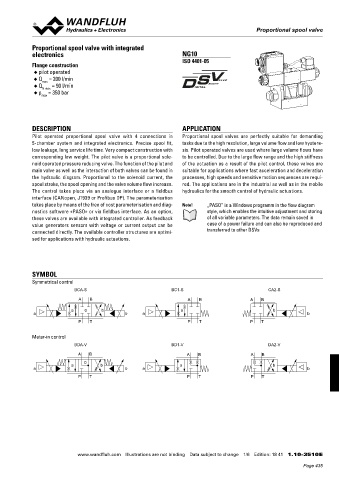
Proportional spool valve
                                                                                           Proportional spool valve


            Proportional spool valve with integrated
            electronics                                          NG10
                                                                 ISO 4401-05
            Flange construction
             ◆  pilot operated
             ◆  Q  = 200 l/min
                max
             ◆  Q N max  = 90 l/min
             ◆  p  = 350 bar
                max


            DESCRIPTION                                          APPLICATION
            Pilot  operated  proportional  spool  valve  with  4  connections  in   Proportional  spool  valves  are  perfectly  suitable  for  demanding
            5-chamber  system  and  integrated  electronics.  Precise  spool  fit,   tasks due to the high resolution, large volume flow and low hystere-
            low leakage, long service life time. Very compact construction with   sis. Pilot operated valves are used where large volume flows have
            corresponding low weight. The pilot valve is a proportional sole-  to be controlled. Due to the large flow range and the high stiffness
            noid operated pressure reducing valve. The function of the pilot and   of the actuation as a result of the pilot control, these valves are
            main valve as well as the interaction of both valves can be found in   suitable for applications where fast acceleration and deceleration
            the  hydraulic  diagram.  Proportional  to  the  solenoid  current,  the   processes, high speeds and sensitive motion sequences are requi-
            spool stroke, the spool opening and the valve volume flow increase.   red. The applications are in the industrial as well as in the mobile

            The  control  takes  place  via  an  analogue  interface  or  a  fieldbus    hydraulics for the smooth control of hydraulic actuations.
            interface (CANopen, J1939 or Profibus DP). The parameterisation
            takes place by means of the free of cost parameterisation and diag-  Note!  „PASO” is a Windows programm in the flow diagram
            nostics software «PASO» or via fieldbus interface. As an option,   style, which enables the intuitive adjustment and storing
            these valves are available with integrated controller. As feedback   of all variable parameters. The data remain saved in
            value  generators  sensors  with  voltage  or  current  output  can  be   case of a power failure and can also be reproduced and
            connected directly. The available controller structures are optimi -  transferred to other DSVs
            sed for applications with hydraulic actuations.


            SYMBOL
            Symmetrical control
                           BCA-S                             BC1-S                             CA2-S
                             A   B                                 A   B                 A   B
                          a    0     b                           a                               b
             a                               b     a                                                         b
                             P   T                                 P   T                 P   T

            Meter-in control
                           BDA-V                             BD1-V                             DA2-V
                            A   B                                  A   B                 A   B
                               0
                          a         b                           a                                b
             a                               b     a                                                         b
                            P   T                                  P   T                 P   T


                            www.wandfluh.com  Illustrations are not binding  Data subject to change  1/6  Edition: 18 41  1.10-3510 E
                                                                                                            Page 435