
Page 436 - Softbound_Edition_19_en
P. 436
Proportional spool valve
Proportional spool valve Proportional spool valve
SYMBOL GENERAL SPECIFICATIONS HYDRAULIC SPECIFICATIONS
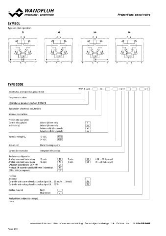
Types of pilot operation Designation Proportional spool valve Working pressure p = 350 bar
max
ti xi xe ae Construction Pilot operated Tank pressure p = 160 bar (type of pilot operation
T max
Mounting Flange construction ae and xi)
A B A B A B A B
Nominal size NG10 according to ISO 4401-05 p T max = 100 bar (type of pilot operation ti
Actuation Proportional solenoid and xe)
Ambient temperature -20…+65 °C Pilot pressure p = 25...350 bar
v
A B A B A B A B The upper temperature limit is a Connection X:
a b a b a b a b guideline for typical applications, in p = 25...200 bar
v
individual cases it may also be higher or Pressure pilot oil drain Minimum 25 bar lower than p v
lower. The electronics of the valve limit Maximum volume flow Q max = 200 l/min, see characteristics
P X Y T P X Y T P X Y T P X Y T the power in case of a too high Leakage oil See characteristics
electronics temperature. More detailed Fluid Mineral oil, other fluid on request
information can be obtained from the Viscosity range 12 mm /s…320 mm /s
2
2
operating instructions „DSV”. Temperature range -25…+70 °C (NBR)
Weight 3,5 kg (1 solenoid) fluid -20…+70 °C (FKM)
3,9 kg (2 solenoids) Contamination Class 18 / 16 / 13
TYPE CODE MTTFd 150 years efficiency
WVP F A10 - - 90 - - / M E - # Filtration Required filtration grade ß 6…10 ≥ 75,
Spool valve, pilot operated, proportional see data sheet 1.0-50
Flange construction ELECTRICAL SPECIFICATIONS ACTUATION
International standard interface ISO NG10 Protection class IP67 with suitable mating connector and Pressure reducing valve
closed housing cover MDPFA04-P / AB-25 for BCA-S / BDA-V
Designation of symbols acc. to table MDPFA04-P / A-25 for BC1-S / BD1-V
Ramps Adjustable MDPFA04-P / B-25 for CA2-S / DA2-V
Nominal volume flow Parameterisation Via fieldbus or USB via device receptacle
Supply voltage 12 VDC, 24 VDC
Type of pilot operation:
Control oil supply (x) (x) and (y) internally ti Note! Exact electrical specifications and detailed description
and drain (y) (x) and (y) externally ae of «DSV» electronics can be found on data sheet
(x) internally (y) externally xi 1.13-76.
(x) externally (y) internally xe
Nominal voltage U N 12 VDC G12 ACCESSORIES COMMISSIONING
24 VDC G24
Parameterisation software See start-up For DSV amplifiers as a rule no parameter adjustments by the cusot-
Slip-on coil Metal housing square mer are required. The plugs have to be connected in accordance with
Parameterisation cable for interface Article no. 219.2896 the chapter «Electrical connection».
Connection execution Integrated electronics USB
(from plug type A on Mini B, 3 m)
Hardware configuration Mating connector (plug female) for analog interface Controllers are supplied configured as amplifiers. The adjustment of
Analog command value signal 12 pole A2 7 pole D2 (-10 … 10 V preset) the mode of control and of the controller are carried out by the custo-
Analog command value signal 12 pole A4 7 pole D4 (4 … 20 mA preset) straight, soldering contact M23, 12 Article no. 219.2330 mer by means of the software adjustment (USB interface, Mini B).
CANopen according to DSP-408 C1 pole Further information can be found on: «www.wandfluh.com».
Profibus DP according to Fluid Power Technology P1 Free- of charge download of the «PASO» software and the operation
CAN J1939 (on request) J1 straight, soldering contact, 7 pole Article no. 219.2335
angled, soldering contact M23, 12 pole Article no. 219.2331 instructions for «DSV» hydraulic valves as well as the operation inst-
Function ructions CANopen Protocol resp. Profibus DP Protocol, with Device
Amplifier Profile DSP-408 for «DSV».
Controller with current feedback value signal (0 … 20 mA / 4 … 20 mA) R1 Technical explanations Data sheet 1.0-100
Controller with voltage feedback value signal (0 … 10 V) R2
Hydraulic fluids Data sheet 1.0-50 Note! The mating connectors and the parameterisation cable
Sealing material NBR Filtration Data sheet 1.0-50 are not part of the delivery. Refer to chapter «Accesso-
FKM (Viton) D1 Relative duty factor Data sheet 1.1-430 ries».
Design index (subject to change) Note! Auxiliary conditions for the cable:
1.10-3510 – External diameter 12 pol: 3,5…14,7 mm
– External diameter 7 pol: 8…10 mm
– Wire cross section max. 1 mm 2
– Recommended wire cross section:
0…25 m = 0,75 mm (AWG18)
2
25…50 m = 1 mm (AWG17)
2
www.wandfluh.com Illustrations are not binding Data subject to change 2/6 Edition: 18 41 1.10-3510 E www.wandfluh.com Illustrations are not binding Data subject to change 3/6 Edition: 18 41 1.10-3510 E
Page 436