
Page 434 - Softbound_Edition_19_en
P. 434
Proportional spool valve
Proportional spool valve Proportional spool valve
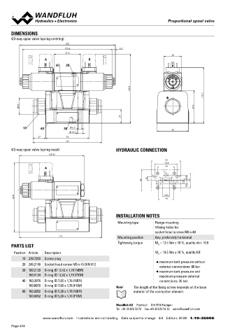
DIMENSIONS Proportional spool valve with integrated
4/3-way spool valve (spring centring) electronics NG10
205 Flange construction ISO 4401-05
192.6 6.2
◆ pilot operated
57.2
38 ◆ Q = 200 l/min
A B ◆ Q max = 90 l/min
N max
60 20 ◆ p = 350 bar
max
146.8 DESCRIPTION APPLICATION
118.3 Pilot operated proportional spool valve with 4 connections in Proportional spool valves are perfectly suitable for demanding
5-chamber system and integrated electronics. Precise spool fit, tasks due to the high resolution, large volume flow and low hystere-
35 69.6 low leakage, long service life time. Very compact construction with sis. Pilot operated valves are used where large volume flows have
corresponding low weight. The pilot valve is a proportional sole- to be controlled. Due to the large flow range and the high stiffness
noid operated pressure reducing valve. The function of the pilot and of the actuation as a result of the pilot control, these valves are
29
main valve as well as the interaction of both valves can be found in suitable for applications where fast acceleration and deceleration
the hydraulic diagram. Proportional to the solenoid current, the processes, high speeds and sensitive motion sequences are requi-
10 40 30 6.5 68 spool stroke, the spool opening and the valve volume flow increase. red. The applications are in the industrial as well as in the mobile
10.5
The control takes place via an analogue interface or a fieldbus hydraulics for the smooth control of hydraulic actuations.
27 93 interface (CANopen, J1939 or Profibus DP). The parameterisation
147 takes place by means of the free of cost parameterisation and diag- Note! „PASO” is a Windows programm in the flow diagram
4/2-way spool valve (spring reset) HYDRAULIC CONNECTION nostics software «PASO» or via fieldbus interface. As an option, style, which enables the intuitive adjustment and storing
138.35 these valves are available with integrated controller. As feedback of all variable parameters. The data remain saved in
case of a power failure and can also be reproduced and
value generators sensors with voltage or current output can be
93 transferred to other DSVs
70.8 connected directly. The available controller structures are optimi -
A 54 sed for applications with hydraulic actuations.
P
X A B Y
68 12 T To 1.5 16.8 46
9.7
SYMBOL
146.8 20.8 Symmetrical control
48
BCA-S BC1-S CA2-S
A B A B A B
INSTALLATION NOTES a 0 b a b
a b a b
Mounting type Flange mounting
4 fixing holes for P T P T P T
socket head screws M6 x 40
176 Mounting position Any, preferably horizontal Meter-in control
Tightening torque M = 13.5 Nm ± 10 %, quality min. 10.9 BDA-V BD1-V DA2-V
PARTS LIST D A B A B A B
Position Article Description M = 10.5 Nm ± 10 %, quality 8.8: 0
D
10 239.7203 Screw plug a a b b a a b b
◆ maximum tank pressure without
20 246.2146 Socket head screw M5 x 45 DIN 912 P T P T P T
external connections: 80 bar
30 160.2120 O-ring ID 12,42 x 1,78 (NBR) ◆ maximum tank pressure and
160.8124 O-ring ID 12,42 x 1,78 (FKM) maximum pressure external
40 160.2076 O-ring ID 7,65 x 1,78 (NBR) connections: 35 bar
160.8076 O-ring ID 7,65 x 1,78 (FKM) Note! The length of the fixing screw depends on the base
60 160.2052 O-ring ID 5,28 x 1,78 (NBR) material of the connection element.
160.6052 O-ring ID 5,28 x 1,78 (FKM)
Wandfluh AG Postfach CH-3714 Frutigen
Tel. +41 33 672 72 72 Fax +41 33 672 72 12 [email protected]
www.wandfluh.com Illustrations are not binding Data subject to change 4/4 Edition: 20 08 1.10-3500 E www.wandfluh.com Illustrations are not binding Data subject to change 1/6 Edition: 18 41 1.10-3510 E
Page 434