
Page 430 - Softbound_Edition_19_en
P. 430
Proportional spool valve
Proportional spool valve Proportional spool valve
DIMENSIONS Proportional spool valve
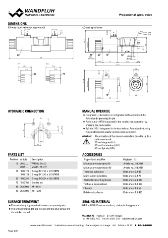
4/3-way spool valve (spring centred) 4/2-way spool valve NG10
Flange construction
A B A 10.5Nm (8.8) ◆ pilot operated ISO 4401-05
MD=
13.5Nm (10.9)
◆ Q = 200 l/min
max
104.5 64 ◆ Q max = 90 l/min
N max
p = 350 bar
◆
W = 70
29
10 70 60 10 50 6.5 DESCRIPTION APPLICATION
307
MD=5Nm 11.5 Pilot operated proportional spool valve with 4 connections in Proportional spool valves are perfectly suitable for demanding
35 72 93.2 14.2
HF1 HS1 214.4 5-chamber system. Precise spool fit, low leakage, long service life tasks due to the high resolution, large volume flow and low hystere-
64.9 71.4 time. Very compact construction with corresponding low weight. sis. Pilot operated valves are used where large volume flows have
51.4 51.4 30 The pilot valve is a proportional solenoid operated pressure redu- to be controlled. Due to the large flow range and the high stiffness
A
80 90 cing valve. The function of the pilot and main valve as well as the of the actuation as a result of the pilot control, these valves are
interaction of both valves can be found in the hydraulic diagram. suitable for applications where fast acceleration and deceleration
105.8 60 Proportional to the solenoid current, the spool stroke, the spool processes, high speeds and sensitive motion sequences are requi-
76 opening and the valve volume flow increase. The proportional spool red. The applications are in the industrial as well as in the mobile
M = valve is not pressure compensated. For the control, Wandfluh hydraulics for the smooth control of hydraulic actuations.
proportional amplifiers are available (see register 1.13).
10 68
35 72
214.4
SYMBOL
HYDRAULIC CONNECTION MANUAL OVERRIDE Symmetrical control
◆ Integrated (–) Actuation pin integrated in the armature tube. BCA-S BC1-S CA2-S
54 Actuation by pressing the pin A B A B A B
◆ Push-button (HF1) Integrated in the knurled nut. Actuation by
P
pressing the push-button a 0 b a b
a b a b
1.5
A B 16.8 ◆ Spindle (HS1) Integrated in the knurled nut. Actuation by turning
46 P T P T P T
9.7 the spindle (continuously variable valve actuation)
T To
Attention! The actuation of the manual override is possible up to a Meter-in control
tank pressure of:
20 bar Integrated (–)
20.8 BDA-V BD1-V DA2-V
24 20 bar Push-button (HF1) A B
80 bar Spindle (HS1) A B A B
a 0 b a b
PARTS LIST ACCESSORIES a b a b
P T P T P T
Position Article Description Proportional amplifier Register 1.13
10 206.3… W.E64 / 31 x 72 Mating connector grey (A) Article no. 219.2001 Types of pilot operation
260.9… M.A60 / 31 x 72 Mating connector black (B) Article no. 219.2002 ti xi xe ae
50 160.2120 O-ring ID 12,42 x 1,78 (NBR) Threaded subplates Data sheet 2.9-40
160.8124 O-ring ID 12,42 x 1,78 (FKM) A B A B A B A B
Multi-station subplates Data sheet 2.9-70
60 160.2282 O-ring ID 28.24 x 2.62 (NBR)
Horizontal mounting blocks Data sheet 2.9-110
70 154.2706 Knurled nut
Technical explanations Data sheet 1.0-100
80 253.7006 HF1-M24 A B A B A B A B
Filtration Data sheet 1.0-50 a b a b a b
90 253.7005 HS1-M24 a b
Relative duty factor Data sheet 1.1-430
P X Y T P X Y T P X Y T P X Y T
SURFACE TREATMENT SEALING MATERIAL
◆ The valve body is painted with a two component paint NBR or FKM (Viton) as standard, choice in the type code
◆ The armature tube, the slip-on coil and the plug screw are
zinc-nickel coated
Wandfluh AG Postfach CH-3714 Frutigen
Tel. +41 33 672 72 72 Fax +41 33 672 72 12 [email protected]
www.wandfluh.com Illustrations are not binding Data subject to change 4/4 Edition: 21 22 1.10-3400 E www.wandfluh.com Illustrations are not binding Data subject to change 1/4 Edition: 20 08 1.10-3500 E
Page 430