
Page 425 - Softbound_Edition_19_en
P. 425
Proportional spool valve
Proportional spool valve
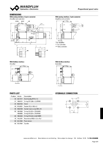
DIMENSIONS
With analog interface, 12 pole connector With analog interface, 7 pole connector
Amplifier and controller Amplifier and controller
25,30 20,21 40 X2
X2
MD= 5.2Nm X1 ** X1 *
X1 ** X1 *
X4 *** 129.4 X4 ***
111.4 9.5 8
5.2 79
45 49 45
41
70 60 50
MD=5Nm 8.6
12.5 18.8 53 68 * For amplifier
224
** For controller
HF1 HS1
51 57 *** Only controller
37 37
80 90
With fieldbus interface With fieldbus interface
Amplifier Controller
X2 X2
X1 X1
X3 X3
111.4
129.4 X4
45
45
7.7
7.7
PARTS LIST HYDRAULIC CONNECTION
Position Article Description
17.8
20 223.1317 Dummy plug M16 x 1,5
21 160.6131 O-ring ID 13,00 x 1,5 (FKM) T
25 062.0102 Cover 31 A B 21 32.5
30 072.0021 Gasket 33,2 x 59,9 x 2
40 208.0100 Socket head screw M4 x 10 P
21.5
50 160.2093 O-ring ID 9,25 x 1,78 (NBR) 40.5
160.6092 O-ring ID 9,25 x 1,78 (FKM)
60 160.2222 O-ring ID 22,22 x 2,62 (NBR)
70 154.2701 Knurled nut M23 x 1,5 x 19,7
80 253.7004 Push-button
90 253.7002 Spindle
www.wandfluh.com Illustrations are not binding Data subject to change 5/6 Edition: 19 29 1.10-3340 E
Page 425