Page 432 - Softbound_Edition_19_en
P. 432

Proportional spool valve
                                                                                     Proportional spool valve                                                                                                     Proportional spool valve


       TYPE CODE                                                                                                                   PERFORMANCE SPECIFICATIONS
                                                                                                                                                    2
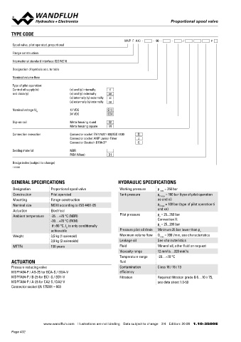
                                                              WVP  F  A10  -     -  90  -     -     /           #                  Oil viscosity u = 30 mm /s
       Spool valve, pilot operated, proportional                                                                                    ∆p = f (Q)  Pressure drop / flow characteristic over 2 control   Q = f (I)  Volume flow signal characteristics over 2 control
                                                                                                                                              edges                                                edges
       Flange construction
                                                                                                                                              [Types: BCA-S, BC1-S, CA2-S, BDA-V, BD1-V,           [Types: BCA-S, BC1-S, CA2-S, BDA-V, BD1-V,
       International standard interface ISO NG10                                                                                              DA2-V]                                               DA2-V]

       Designation of symbols acc. to table                                                                                            ∆p [bar]                                             Q [l/min]
                                                                                                                                        K4249                                                 K4129                 100,~200 bar  50 bar
                                                                                                                                                                                          200
       Nominal volume flow                                                                                                            40                                                  160                                    30 bar
                                                                                                                                      30                                                                                         20 bar
       Type of pilot operation:                                                                                                                                                           120
       Control oil supply (x)       (x) and (y) internally   ti                                                                       20                                                   80                                    10 bar
       and drain (y)                (x) and (y) externally   ae                                                                       10                                                   40
                                    (x) internally (y) externally   xi
                                    (x) externally (y) internally   xe                                                                0                                                     0
                                                                                                                                        0  20  40  60  80  100 120  140  160 180 200  Q [l/min]  20  30  40  50  60  70  80  90  100  I [%]
       Nominal voltage U N          12 VDC            G12
                                    24 VDC            G24
                                                                                                                                    Q  = f (p)  Leakage volume flow characteristics main stage  Q  = f (p)  Leakage volume flow pilot control stage
       Slip-on coil                 Metal housing round   W                                                                          L                                                    L
                                    Metal housing square   M                                                                                  per control edge
                                                                                                                                        Q [ml]                                             @ 350 bar, pred 0 bar:   100 ml/min
       Connection execution         Connector socket EN 175301-803/ISO 4400   D                                                      400  K2092
                                    Connector socket AMP Junior-Timer   J                                                            350                                                   @ 350 bar, pred 25 bar: 320 ml/min
                                    Connector Deutsch DT04-2P        G                                                               300
                                                                                                                                     250
       Sealing material             NBR                                                                                              200
                                    FKM (Viton)        D1                                                                            150
                                                                                                                                     100
       Design index (subject to change)                                                                                               50                                                Note!    All values were measured over two control edges. The
                                                                                                                                       0
       1.10-3500                                                                                                                         0   50   100  150  200  250  300  350 p [bar]           connections A and B were short-circuited.

       GENERAL SPECIFICATIONS                              HYDRAULIC SPECIFICATIONS
       Designation        Proportional spool valve          Working pressure   p   = 350 bar
                                                                                max                                                ACCESSORIES                                          STANDARDS
       Construction       Pilot operated                    Tank pressure      p    = 160 bar (type of pilot operation
                                                                                T max
       Mounting           Flange construction                                  ae and xi)                                           Fixing screws                Data sheet 1.0-60       Mounting interface  ISO 4401-05
       Nominal size       NG10 according to ISO 4401-05                        p T max  = 100 bar (type of pilot operation ti       Threaded subplates           Data sheet 2.9-40       Solenoids           DIN VDE 0580
       Actuation          Electrical                                           and xe)                                              Multi-station subplates      Data sheet 2.9-70       Connection execution D  EN 175301 – 803
       Ambient temperature  -25…+70 °C (NBR)                Pilot pressure     p  = 25...350 bar                                    Horizontal mounting blocks   Data sheet 2.9-110      Protection class    EN 60 529
                                                                                v
                          -20…+70 °C (FKM)                                     Connection X:                                        Technical explanations       Data sheet 1.0-100      Contamination efficiency  ISO 4406
                           if >50 °C, I  is only conditionally                 p  = 25...200 bar                                    Filtration                   Data sheet 1.0-50
                                                                                v
                                  G
                          achievable                        Pressure pilot oil drain  Minimum 25 bar lower than p v
       Weight             3,5 kg (1 solenoid)               Maximum volume flow  Q  max  = 200 l/min, see characteristics
                          3,9 kg (2 solenoids)              Leakage oil        See characteristics
       MTTFd              150 years                         Fluid              Mineral oil, other fluid on request
                                                                                   2
                                                            Viscosity range    12 mm /s…320 mm /s                                  SURFACE TREATMENT                                    SEALING MATERIAL
                                                                                            2
                                                            Temperature range   -20…+70 °C                                          ◆  The main valve body, the screw plugs, the slip-on coil and the   NBR or FKM (Viton) as standard, choice in the type code
       ACTUATION                                            fluid                                                                     armature tube are zinc-nickel coated
       Pressure reducing valve                              Contamination      Class 18 / 16 / 13                                   ◆  The pilot valve body is coated with a two component paint
       MDPFA04-P / AB-25 for BCA-S / BDA-V                  efficiency
       MDPFA04-P / B-25 for BC1-S / BD1-V                   Filtration         Required filtration grade ß 6…10 ≥ 75,
       MDPFA04-P / A-25 for CA2-S / DA2-V                                      see data sheet 1.0-50
       Connector socket EN 175301 – 803


                       www.wandfluh.com  Illustrations are not binding  Data subject to change  2/4  Edition: 20 08  1.10-3500 E                   www.wandfluh.com  Illustrations are not binding  Data subject to change  3/4  Edition: 20 08  1.10-3500 E
       Page 432
   427   428   429   430   431   432   433   434   435   436   437