
Page 439 - Softbound_Edition_19_en
P. 439
Proportional spool valve
Proportional spool valve
PERFORMANCE SPECIFICATIONS
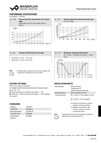
Oil viscosity u = 30 mm /s
2
∆p = f (Q) Pressure drop / flow characteristic over 2 control Q = f (p) Leakage volume flow characteristics main stage
L
edges per control edge
[Types: BCA-S, BC1-S, CA2-S, BDA-V, BD1-V, Q [ml]
DA2-V] 400 K2092
Δp [bar] 350
300
K4128
250
40 200
150
30 100
50
20 0
10 0 50 100 150 200 250 300 350 p [bar]
0
0 20 40 60 80 100 120 140 160 180 200 Q [l/min]
Q = f (p) Leakage volume flow pilot control stage Q = f (s, x) Volume flow adjustment characteristics
L
∆p = 10 bar, s = command value signal, x = spool
stroke
@ 350 bar, pred 0 bar: 100 ml/min
@ 350 bar, pred 25 bar: 320 ml/min Q [l/min]
100 K4203
90
80
70
60
50
40
Note! All values were measured over two control edges. The 30
20
connections A and B were short-circuited. 10
0
-100 -80 -60 -40 -20 0 20 40 60 80 100 x [%]
→
→
-100 -73 -45 -18 -4 0 0 0 4 18 45 73 100 s [%]
FACTORY SETTINGS INSTALLATION NOTES
Dither set for optimum hysteresis Mounting type Flange mounting
◆ = Deadband: Both solenoids switched off at command value 4 fixing holes for
signal -2%… 2% socket head screws M6 x 40
● = Opening pressure at command value signal + / - 4% Mounting position Any, preferably horizontal
■ = Flow at ∆p = 10 bar over two control edges + / - 70% command Tightening torque M = 13.5 Nm ± 10 %, quality min. 10.9
value signal D
M = 10.5 Nm ± 10 %, quality 8.8:
D
STANDARDS ◆ maximum tank pressure without
external connections: 80 bar
CANopen DRP 303-1 ◆ maximum tank pressure and
Profibus DP IEC 947-5-2 maximum pressure external
Mounting interface ISO 4401-05 connections: 35 bar
Protection class EN 60 529 Note! The length of the fixing screw depends on the base
Contamination ISO 4406 material of the connection element.
efficiency
www.wandfluh.com Illustrations are not binding Data subject to change 5/6 Edition: 18 41 1.10-3510 E
Page 439