
Page 442 - Softbound_Edition_19_en
P. 442
Proportional spool valve
Proportional spool valve Proportional spool valve
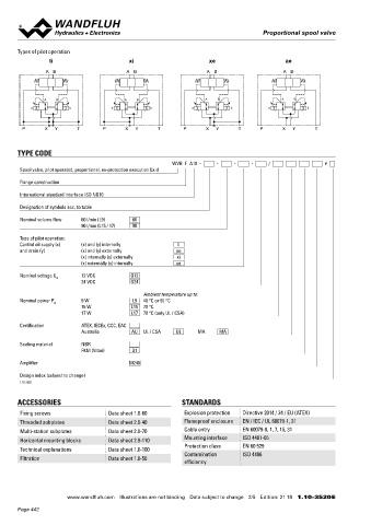
Types of pilot operation GENERAL SPECIFICATIONS HYDRAULIC SPECIFICATIONS
ti xi xe ae Designation Proportional spool valve Working pressure p = 350 bar
max
A B A B A B A B Construction Pilot operated Tank pressure p = 160 bar (type of pilot operation
T max
Mounting Flange construction ae and xi)
Nominal size NG10 according to ISO 4401-05 p T max = 100 bar (type of pilot operation ti
Actuation Ex-protection proportional solenoid and xe)
A B A B A B A B Pilot pressure p = 25...350 bar
Ambient temperature Operation as T6 v
a b a b a b a b Connection X:
-25…+40 °C (L9)
Operation as T4 p = 25...200 bar
v
P X Y T P X Y T P X Y T P X Y T -25…+90 °C (L9) Pressure pilot oil drain Minimum 25 bar lower than p v
-25…+70 °C (L15 / L17) Maximum volume flow Q = 200 l/min, see characteristics
max
Weight 5,2 kg (1 solenoid) Leakage oil See characteristics
TYPE CODE 7,0 kg (2 solenoids) Fluid Mineral oil, other fluid on request
MTTFd 150 years Viscosity range 12 mm /s…320 mm /s
2
2
WVB F A10 - - - - / # Temperature range Operation as T6
Spool valve, pilot operated, proportional, ex-protection execution Ex d
fluid NBR -25…+40 °C (L9)
Flange construction FKM -20…+40 °C (L9)
Operation as T4
International standard interface ISO NG10 NBR -25…+70 °C (L9 or L15 / L17)
FKM -20…+70 °C (L9 or L15 / L17)
Designation of symbols acc. to table
Contamination Class 18 / 16 / 13
Nominal volume flow 60 l/min (L9) 60 efficiency
90 l/min (L15 / 17) 90 Filtration Required filtration grade ß 6…10 ≥ 75,
see data sheet 1.0-50
Type of pilot operation:
Control oil supply (x) (x) and (y) internally ti
and drain (y) (x) and (y) externally ae Attention! With the execution L9 for ambient temperatures up to 90
(x) internally (y) externally xi °C (L9/90 °C), Q is not reached
(x) externally (y) internally xe N
Nominal voltage U N 12 VDC G12
24 VDC G24
Ambient temperature up to: ELECTRICAL SPECIFICATIONS MANUAL OVERRIDE
Nominal power P N 9 W L9 40 °C or 90 °C Protection class IP65 / 66 / 67 HB4,5 as standard
15 W L15 70 °C Optionally: HN (K)
17 W L17 70 °C (only UL / CSA) Relative duty factor 100 % DF → see data sheet 1.1-311
Voltage tolerance ± 10 % with regard to nominal voltage
Certification ATEX, IECEx, CCC, EAC Standard nominal 12 VDC, 24 VDC
Australia AU UL / CSA UL MA MA
voltage
Sealing material NBR Limiting current at… °C L9, 40 °C SURFACE TREATMENT
FKM (Viton) D1 I = 625 mA (12 VDC) ◆ The main valve body, the distance plate, the screw plugs, the
G
I = 305 mA (24 VDC) slip-on coil and the armature tube are zinc-nickel coated
Amplifier M248 G The pilot valve body is coated with a two component paint
L15 / 17, 50 °C ◆
Design index (subject to change) I = 950 mA (12 VDC)
G
I = 450 mA (24 VDC)
1.10-3520 G
L15 / 17, 70 °C
I = 910 mA (12 VDC) SEALING MATERIAL
G
ACCESSORIES STANDARDS I = 420 mA (24 VDC) NBR or FKM (Viton) as standard, choice in the type code
G
Fixing screws Data sheet 1.0-60 Explosion protection Directive 2014 / 34 / EU (ATEX) Standard nominal 9 W, 15 W, 17 W
Threaded subplates Data sheet 2.9-40 Flameproof enclosure EN / IEC / UL 60079-1, 31 power
Multi-station subplates Data sheet 2.9-70 Cable entry EN 60079-0, 1, 7, 15, 31 Temperature class Nominal power 9 W: T1…T6
Nominal power 15 W / 17 W: T1…T4
Horizontal mounting blocks Data sheet 2.9-110 Mounting interface ISO 4401-05
Protection class EN 60 529 Note! Other electrical specifications see data sheet 1.1-183
Technical explanations Data sheet 1.0-100 and 1.1-184
Filtration Data sheet 1.0-50 Contamination ISO 4406
efficiency
www.wandfluh.com Illustrations are not binding Data subject to change 2/5 Edition: 21 18 1.10-3520 E www.wandfluh.com Illustrations are not binding Data subject to change 3/5 Edition: 21 18 1.10-3520 E
Page 442